System and method for an efficient rotor for an electric motor

a technology of efficient rotor and electric motor, which is applied in the manufacture of stator/rotor bodies, slip-ring manufacturing, and solid insulation. it can solve the problems of inability to achieve the same resistance of conventional brazing techniques used for copper, inability to cast copper, and inability to meet the requirements of reducing the resistance of electrical connections. , to achieve the effect of reducing the electrical resistance, minimizing the electrical resistance, and tightening the toleran

Active Publication Date: 2007-12-13
TESLA INC
View PDF2 Cites 15 Cited by
  • Summary
  • Abstract
  • Description
  • Claims
  • Application Information

AI Technical Summary

Benefits of technology

[0012]The assembly is heated in a furnace to allow the silver coating on the slugs to braise the slugs to the portion of the bars facing the slugs. As the assembly is heated, the forces, optionally spring loaded, and the limited thermal expansion of the steel pieces will ensure the slugs and bars will stay in close contact, even as the thermal expansion of them occurs, but will allow the thermal expansion to occur without failure of the assembly: the wires serve the same purpose. The close contact ensures that more of the surface of the slugs is brazed to the bars, minimizing the electrical resistance between them. The assembly is then reduced in temperature according to an annealing schedule. The green chromate stainless steel plates, collets and collars or wires, and the nuts and bolts used to cause the plates and collars to exert the clamping force, are removed.
[0013]Because the slugs are inserted radially, tighter tolerances can be achieved between the slugs and the bars, reducing the electrical resistance from that which can be achieved using a cap plate. However, without the weight of the cap, inertial resistance is lowered.
[0014]The rotor assembly can then be cooled to cause it to reduce slightly in dimension and a Beryllium copper band is heated to expand it. The band is slipped over the ends of the rotor approximately at the midpoint of the slugs. The assembly is then brought to room temperature. As the band cools, it contracts, which compresses it around the rotor, which expands as its temperature rises to room temperature. The band prevents the now annealed copper bars and slugs from deforming during the rotation of the rotor.

Problems solved by technology

However, the heavier the motor is, the more inertial resistance that motor will have, and so a heavier motor may not be as efficient as a lighter motor with the same dimensions.
Because aluminum is lighter than copper, it has a lower inertial resistance, but because aluminum is not as good a conductor as copper, motors built from aluminum can have a higher electrical resistance than they could if they were built using an identical geometry of copper, at least partially offsetting the inertial efficiency.
Conventional brazing techniques used for copper may not produce an electrical connection with resistance that is as low.
Cast copper could have the benefits of the lower resistance of copper, while achieving the higher conductivity of casting, but casting copper requires temperatures that could damage the laminated discs, and thus, cast copper conductors and connections between the conductors have not been frequently used in this manner.
However, because casting copper is impractical, brazing the copper bars together to form the end rings of the rotor continues to be used.
However, because the fins of the cap piece must be slipped in between the bars all at the same time, the tolerances of the fins occupying the spaces between the bars can not be significantly tight, increasing the resistance of the electrical connection.
Although the resistance between the bars of such a construction can be lower than braising, it can still be significant.
Furthermore, the cast connections at the ends can add enough weight to the rotor to increase its inertial resistance, reducing the efficiency of the rotor.

Method used


Image

  • System and method for an efficient rotor for an electric motor
  • System and method for an efficient rotor for an electric motor
  • System and method for an efficient rotor for an electric motor

Examples


Embodiment Construction

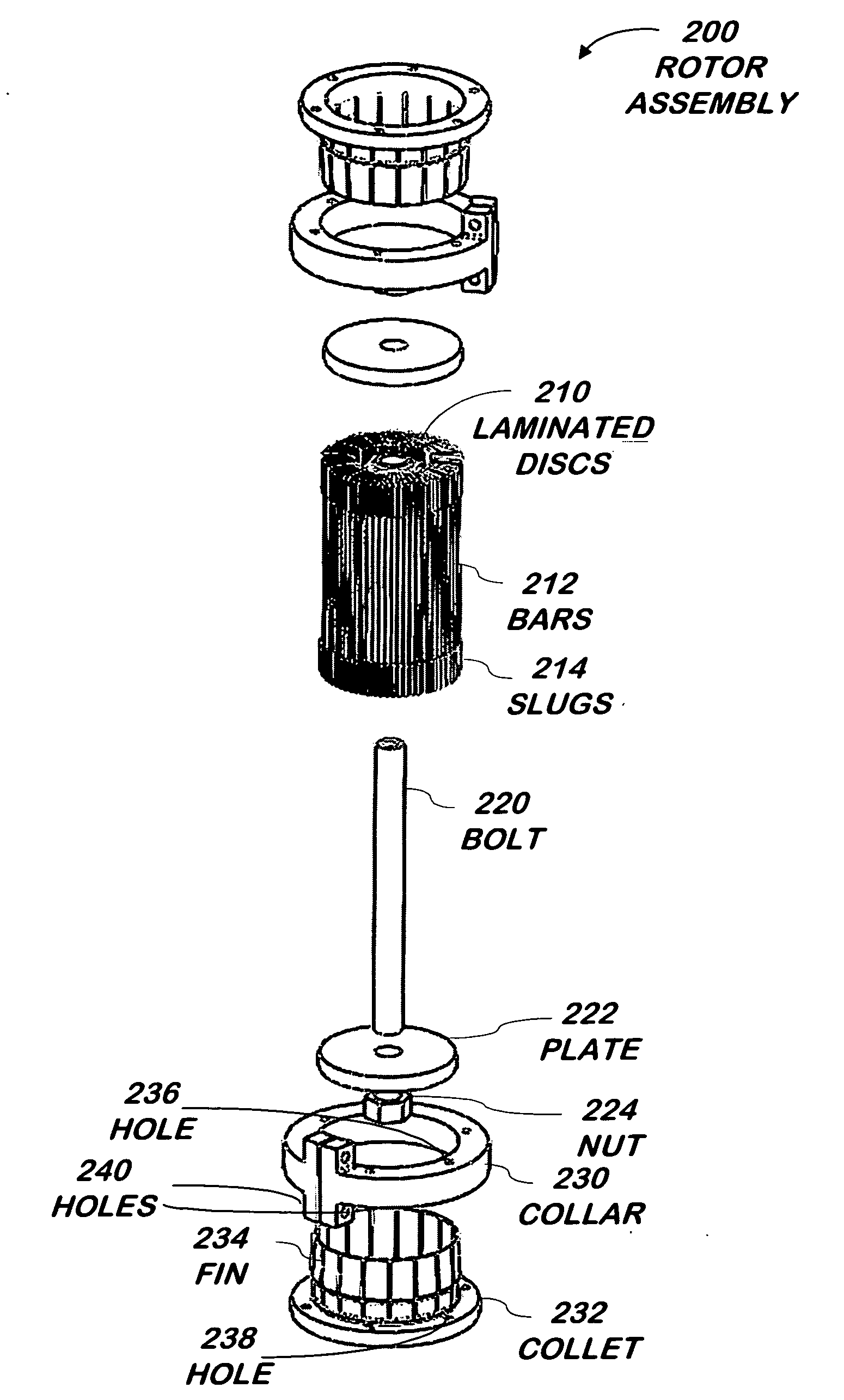
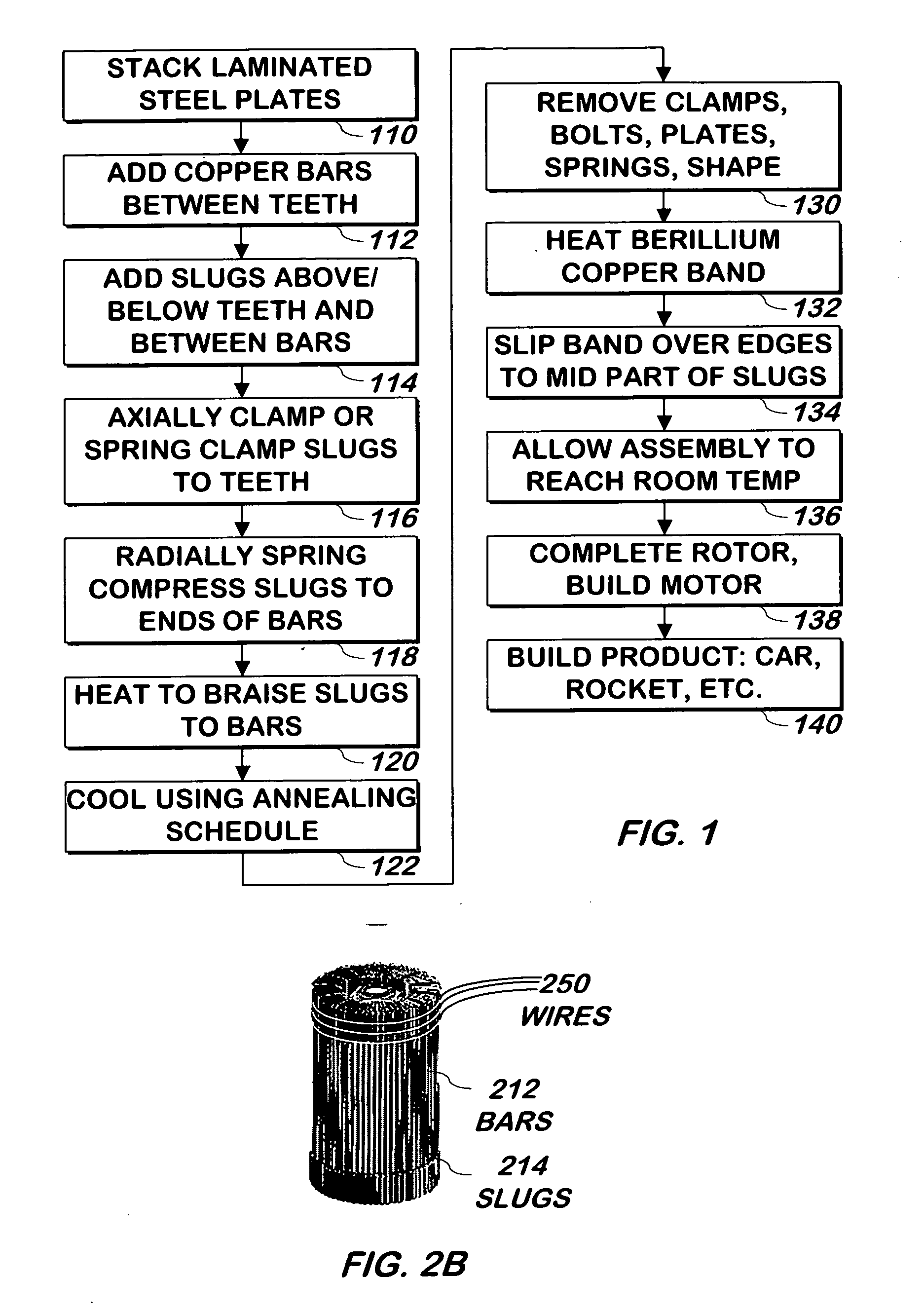
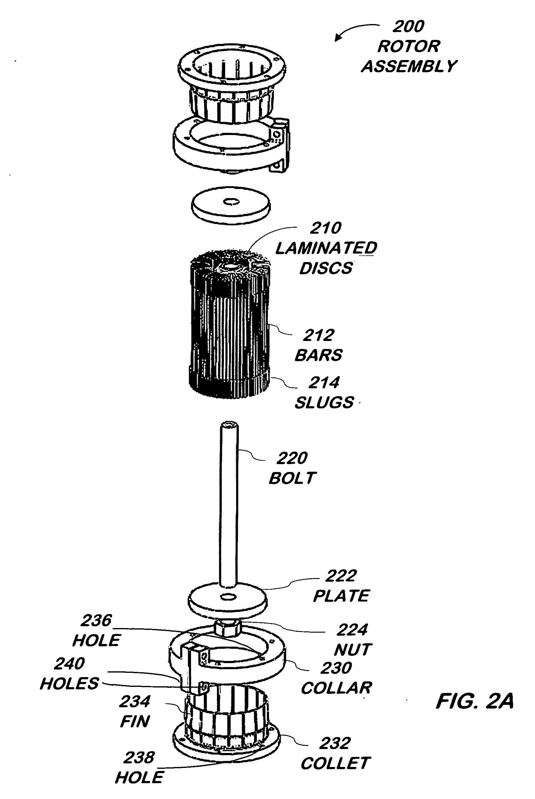
[0020]FIG. 1 is a flowchart illustrating a method of assembling an electric motor according to one embodiment of the present invention. FIG. 2A is a diagram of an exploded view of a rotor according to one embodiment of the present invention. FIG. 2B is a diagram of a portion of the rotor of FIG. 2A according to another embodiment of the present invention. The method of FIG. 1 is described alongside the diagrams of FIGS. 2A and 2B, however, the rotor and method may be practiced independently of one another: e.g. the method of FIG. 1 may be used on a rotor different from that shown in FIG. 2A or 2B and vice versa.

[0021]Referring now to FIGS. 1, 2A and 2B, laminated steel discs 210 are stacked 110. A representative disc 210 is shown in more detail in FIG. 3. Referring now to FIGS. 1, 2A, 2B, and 3, in one embodiment, each of the discs 210 is substantially round in shape, and each of the discs has teeth 310 radiating outwards from a central portion. In one embodiment, the teeth 310 have...


PUM

PropertyMeasurementUnit
lengthaaaaaaaaaa
heightaaaaaaaaaa
radial forceaaaaaaaaaa

Abstract

A rotor assembly for an electric motor is constructed by adding bars made out of a conducting material such as copper, to spaces between the teeth of a stack of discs, inserting bars referred to as “slugs”, also made out of a conducting material such as copper, in the spaces between the bars on either side of the stack of discs, radially compressing the bars and discs, one or both of which are plated or otherwise coated with a braising material, and then heating the rotor to allow the bars to be braised to the slugs.

Description

FIELD OF THE INVENTION[0001]The present invention is related to electric motors and more specifically to rotor construction in an electric motor.BACKGROUND OF THE INVENTION[0002]The rotor of conventional electric motors is built using a stack of laminated magnetic steel discs. The lamination prevents the flow of currents between the discs that can interfere with the efficiency of the rotor. The discs have numerous teeth radiating out from a circular portion, with spaces in between the teeth. The discs are stacked with the teeth above one another, forming a cylinder with deep grooves formed by the spaces between the teeth of the discs.[0003]Conductors such as aluminum or copper are added to the grooves, either by inserting aluminum or copper bars into the grooves, or casting molten aluminum into the grooves. The conductors are longer than, and thus stick out from the ends of, the stacked discs. At either end, the conductors are electrically connected to one another: in the case of ca...

Claims


Application Information

Patent Timeline
Patent Type & Authority Applications(United States)
IPC IPC(8): H02K9/20
CPCH02K15/0081Y10T29/49011Y10T29/49012Y10T29/49009
Inventor LYONS, DAVIDSTRAUBEL, JEFFREY B.SHAHOIAN, ERIKGARRIGA, RUDY
Owner TESLA INC
Why Eureka
Try Eureka