Driving circuit

Inactive Publication Date: 2007-12-13
DENSO CORP
View PDF4 Cites 7 Cited by
  • Summary
  • Abstract
  • Description
  • Claims
  • Application Information

AI Technical Summary

Benefits of technology

[0008]It is therefore an object of the invention to provide a driving circuit that drives multiple semiconductor switching devices by common driving voltage, wherein short-ci

Problems solved by technology

As a result, the gate voltage of the other device also drops, and the fault that occurred in one device has an influence on the other device.
Thus, gate-source short-circuit failure can be detected using the above output monitor circuit.
However, in cases where break failure has occurred or is about to occur in a load, the drain-source voltage is constantly low regardless of the level of a driving signal.
It is difficult to

Method used


Image

  • Driving circuit
  • Driving circuit
  • Driving circuit

Examples


first embodiment

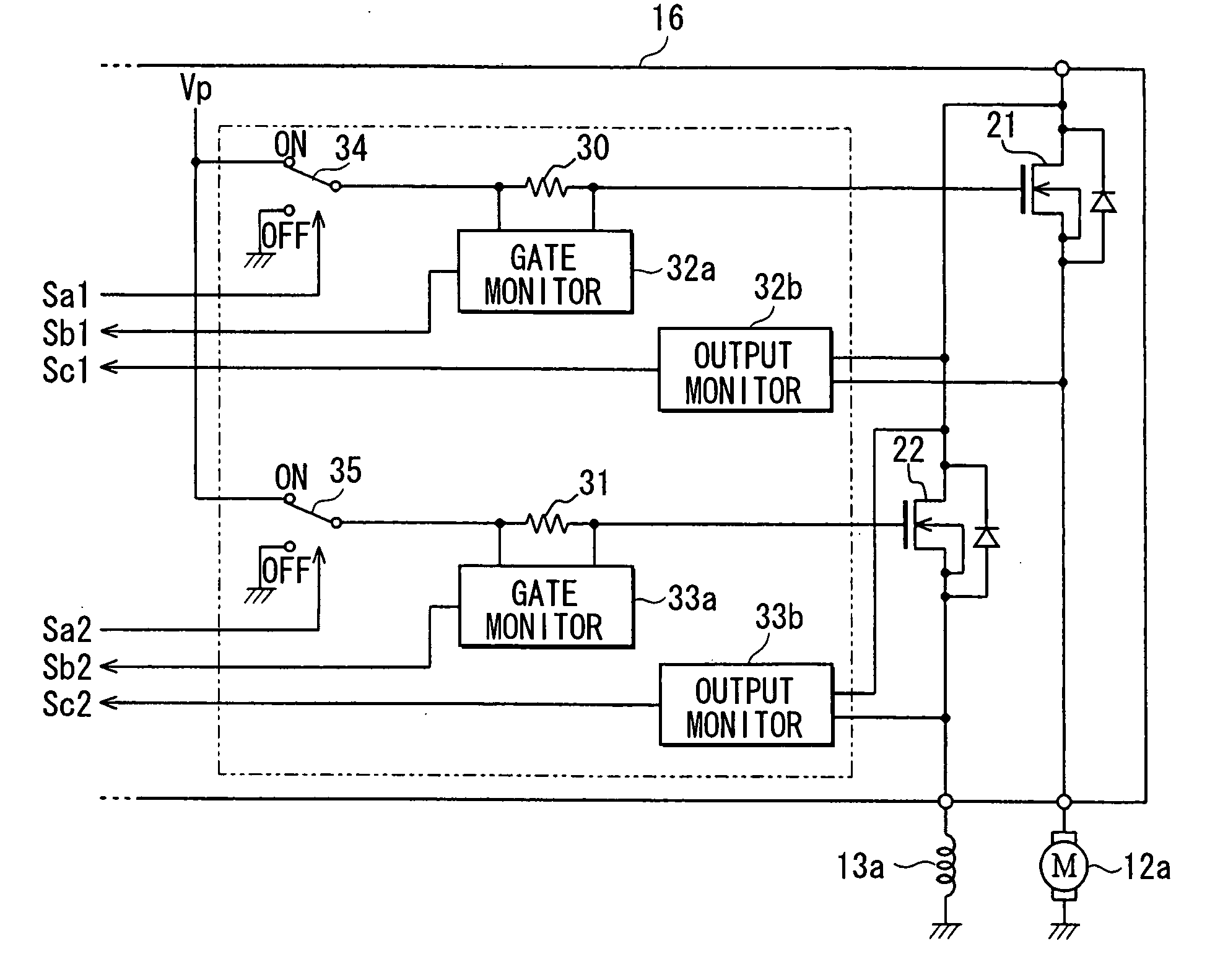
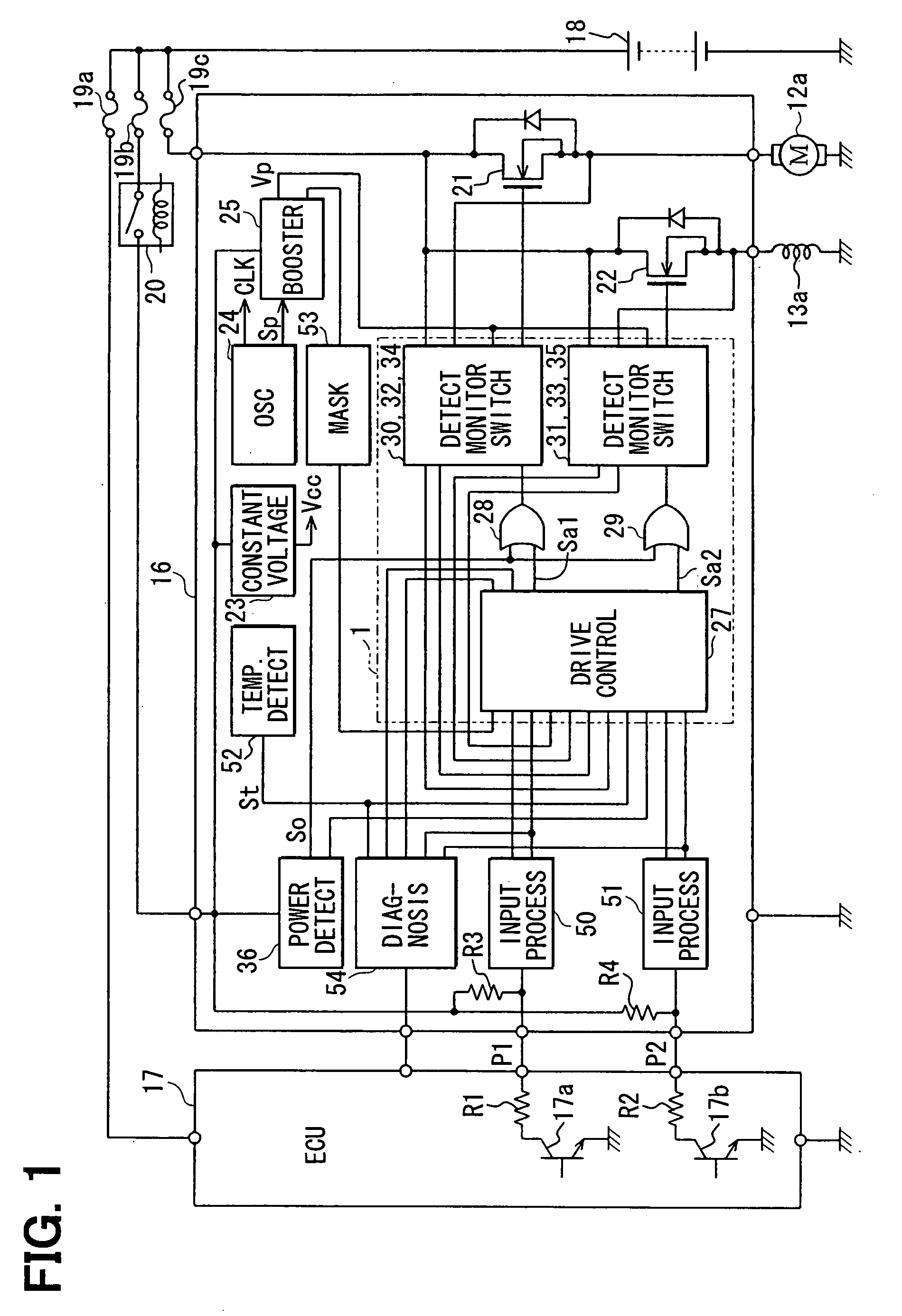
[0020]Referring first to FIG. 1, a driving circuit according to a first embodiment is shown with reference numeral 1 as a part of a driving device 16, which drives electric loads such as an electric motor 12a and an electromagnetic coil 13a with electric power of a vehicle-mounted battery 18. The electric motor 12a and the electromagnetic coil 13a are used in a secondary air supply system of a multi-cylinder gasoline engine 100 as shown in FIG. 5.

[0021]In the example illustrated in FIG. 5, an intake pipe 2 of the engine 100 is provided at its most upstream portion with an air filter 3, and a throttle valve 4 is provided downstream the air filter 3. A fuel injection valve, not shown, is disposed in proximity to the intake ports of an intake manifold 5 of the engine 100. In an exhaust pipe 6 of the engine 100, for example, a three-way catalyst 7 is disposed for purifying exhaust gas. Upstream of this catalyst 7, an O2 sensor 8 is disposed for detecting the concentration of oxygen in e...

second embodiment

[0054]In a second embodiment, as shown in FIG. 6, a driving circuit 1a drives two MOSFETs 21, 22 that function as high-side switches, based on the common boosted voltage Vp supplied from the booster circuit 25. Resistors 12b, 13b respectively represent loads connected between the sources of the MOSFETs 21, 22 and ground.

[0055]Constant voltage circuits 58, 59 are inputted with the boosted voltage Vp and output a constant driving voltage Vc, and are individually provided for the MOSFETs 21, 22. In the driving current path from the booster circuit 25 to the constant voltage circuit 58, there are provided the switching circuit 34 (corresponding to first switching circuit) and the resistor 30 (corresponding to current detection circuit) in series. In the driving current path from the constant voltage circuit 58 to the gate of the MOSFET 21, there is provided a switching circuit 60 (corresponding to second switching circuit). The gate monitor circuit 32a outputs the drive abnormality dete...

third embodiment

[0061]In a third embodiment, as shown in FIG. 7, in a driving circuit 1b, the switching circuit 34 is so constructed that it is turned on and off by the output signal of an AND circuit 65 to which the driving signal Sa1 and the drive abnormality detection signal Sb1 are inputted; and the switching circuit 35 is so constructed that it is turned on and off by the output signal of an AND circuit 66 to which the driving signal Sa2 and the drive abnormality detection signal Sb2 were inputted. Also, in this embodiment, the same operation and effect as in the first embodiment are provided. This embodiment may also be applied to the secondary air injection system as the first embodiment.


PUM


Abstract

When a driving signal changes from L level to H level, a switching-circuit is turned on. Then, a gate current flows from a booster circuit to MOSFET through the switching circuit and a resistor. A gate monitor circuit outputs a drive abnormality detection signal of L level when the gate current exceeds a predetermined threshold value. A switching circuit and MOSFET are also similarly driven by a driving signal, and a gate monitor circuit also similarly outputs a drive abnormality detection signal of the L level. When the drive abnormality detection signal changes to the L level, the driving signals are brought to the L level, and the MOSFETs are separated from the booster circuit.

Description

CROSS REFERENCE TO RELATED APPLICATION[0001]This application is based on and incorporates herein by reference Japanese Patent Application No. 2006-98545 filed on Mar. 31, 2006,FIELD OF THE INVENTION[0002]The present invention relates to a driving circuit that drives multiple semiconductor switching devices by a common driving voltage supplied from a driving power source.BACKGROUND OF THE INVENTION[0003]Various electric loads are used in vehicles. For instance, as disclosed in U.S. Pat. No. 7,100,368 (JP 2005-307957A), a motor-driven air pump and an air switching valve are used in a secondary air injection system for introducing secondary air into an exhaust air path upstream of a catalyst for purifying exhaust gas of an engine. This system includes two N-channel power MOSFETs that respectively drive a motor (load) for driving the air pump and an electromagnetic coil (load) for driving an electromagnetic valve; and one booster circuit required for using these MOSFETs as high-side swi...

Claims


Application Information

Patent Timeline
IPC IPC(8): H02H3/08
CPCF01N3/22F02D41/28F02D2041/2058F02D2041/2093H01L2924/0002H01L2924/00
Inventor ITOH, MAKOTO
Owner DENSO CORP
Why Eureka
Try Eureka