

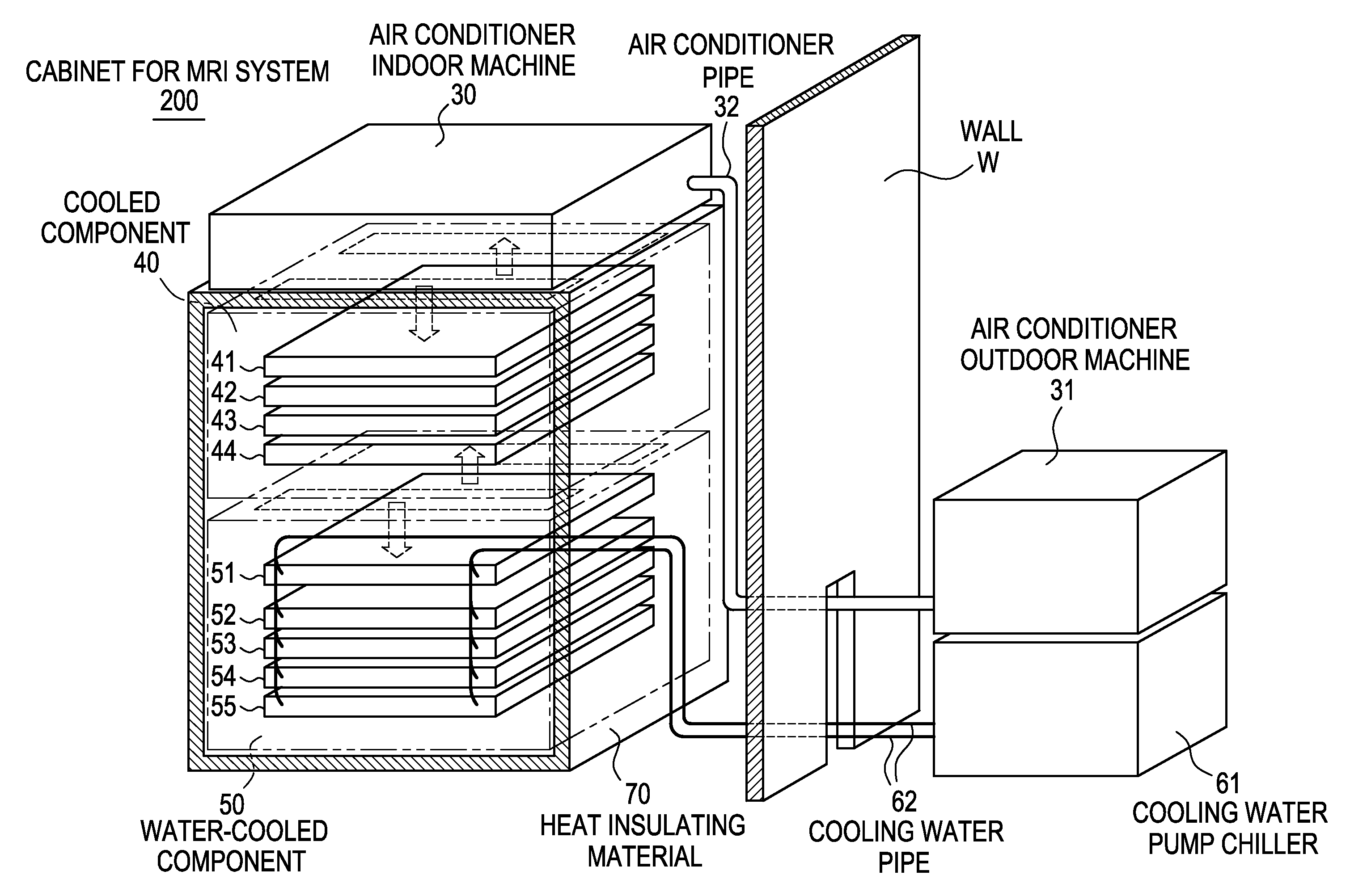
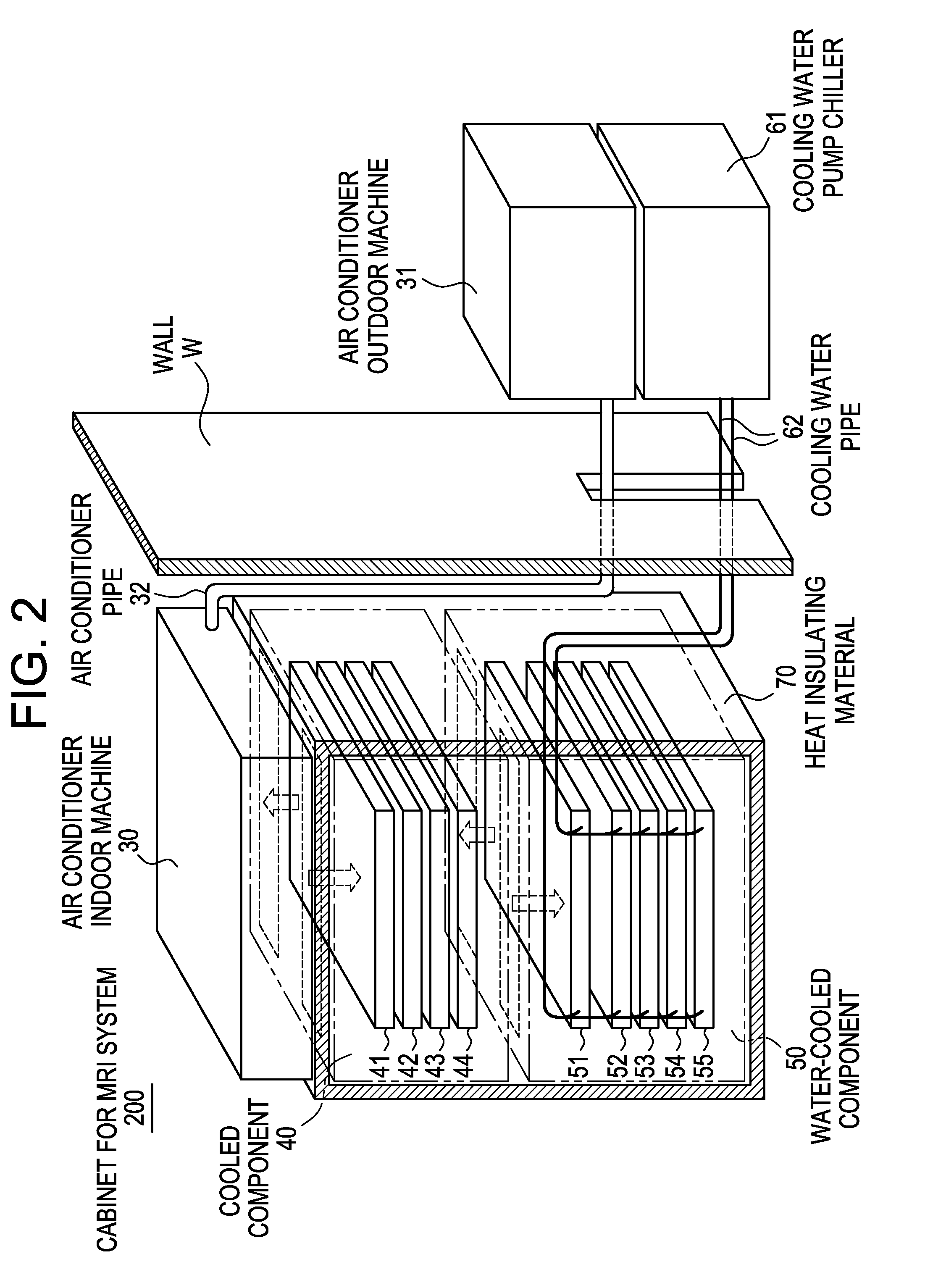
Cabinet for MRI system
a magnetic resonance imaging and cabinet technology, applied in domestic cooling devices, lighting and heating devices, domestic applications, etc., can solve the problems of insufficiency of gradient amplifiers, memory or noise excess,
- Summary
- Abstract
- Description
- Claims
- Application Information
AI Technical Summary
Benefits of technology
Problems solved by technology
Method used
Image

Examples
first embodiment
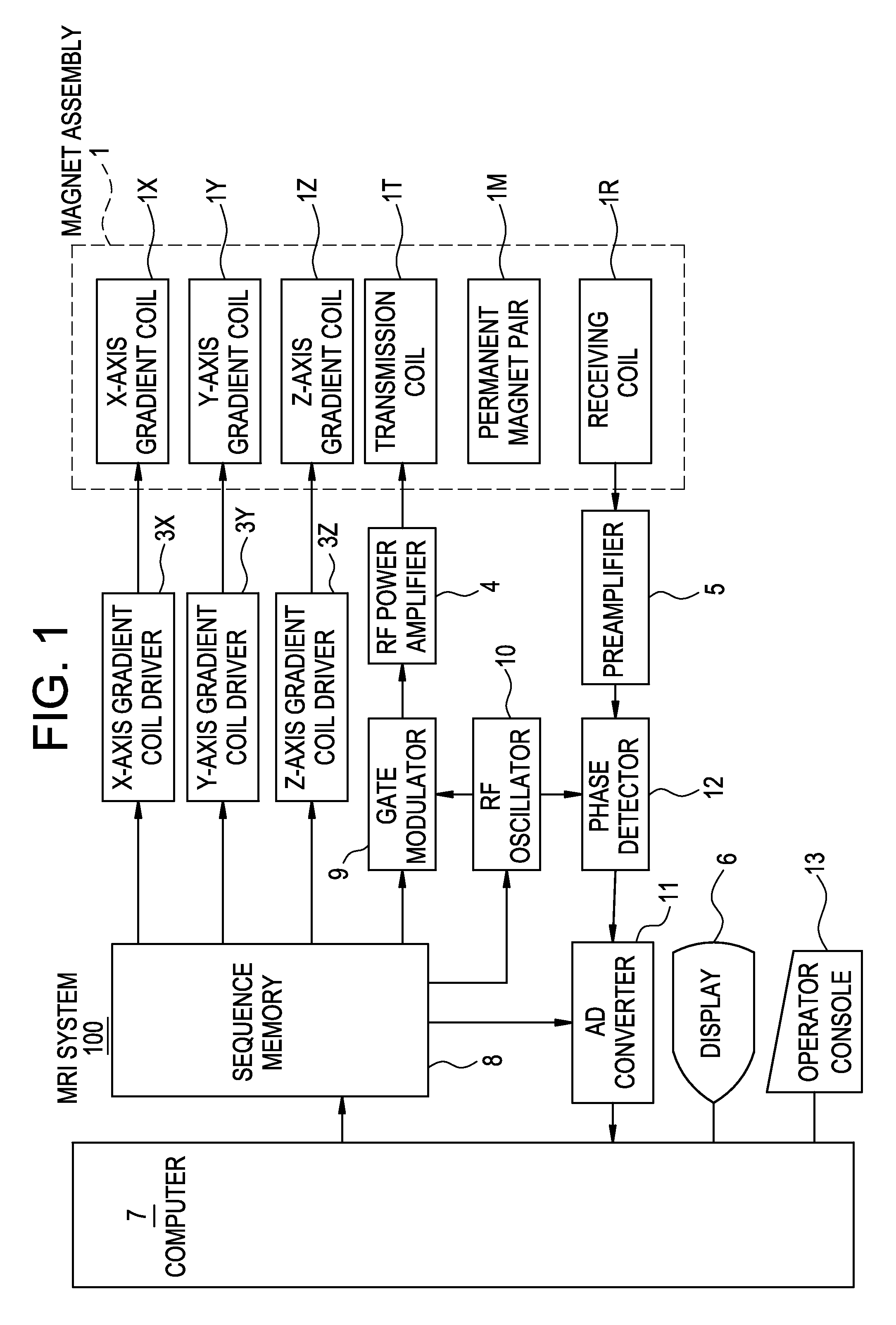
[0037]FIG. 1 is a block diagram showing a functional configuration of an MRI system 100 according to a first embodiment of the invention.
[0038]In the MRI system 100, a magnet assembly 1 has a spatial portion (bore) for insertion therein of a subject and includes, in a surrounding relation to the spatial portion, an X-axis gradient coil 1X for forming an X-axis gradient magnetic field, a Y-axis gradient coil 1Y for forming a Y-axis gradient magnetic field, a Z-axis gradient coil 1Z for forming a Z-axis gradient magnetic field, a transmission coil 1T to provide RF pulses for exciting a spin of an atomic nucleus in the subject, a receiving coil 1R for detecting an NMR signal generated from the subject, and a pair of permanent magnets 1M for forming a static magnetic field.
[0039]Superconducting magnets may be used instead of the pair of permanent magnets 1M.
[0040]The X-axis gradient coil 1X, Y-axis gradient coil 1Y, Z-axis gradient coil 1Z and transmission coil 1T are connected to an X-...
second embodiment
[0058]Propylene glycol or ethylene glycol may be used as cooling water.
PUM
 Abstract
Description
Claims
Application Information