Apparatus and method for downhole dynamics measurements

a technology of dynamics measurement and apparatus, applied in the field of downhole tools, can solve the problems of reducing the penetration rate (rop), affecting the reliability of the sensor system, and often encountering severe dynamic conditions

Inactive Publication Date: 2007-12-20
SCHLUMBERGER TECH CORP
View PDF38 Cites 67 Cited by
  • Summary
  • Abstract
  • Description
  • Claims
  • Application Information

AI Technical Summary

Benefits of technology

[0009]Exemplary embodiments of the present invention may advantageously provide several technical advantages. For example, in one exemplary embodiment, real-time, downhole measurement of stick/slip and other vibration components during drilling enables corrective measures to be implemented when dangerous dynamic conditions are encountered. Moreover, exemp...

Problems solved by technology

It is well known in the art that severe dynamic conditions are often encountered during drilling.
Bit bounce includes axial vibration of the drill string, often resulting in temporary lift off of the drill bit from the formation (“bouncing” of the drill bit off the bottom of the borehole).
Bit bounce is known to reduce the rate of penetration (ROP) during drilling, cause excessive fatigue damage to BHA components, and may even damage the well in extreme conditions.
Such lateral vibrations are commonly recognized as the leading cause of drill string and BHA failures and may be caused, for example, by bit whirl and/or the use of unbalanced drill string components.
In stick/slip conditions a portion of the drill string or bit sticks to the borehole wall due to frictional forces often causing the drill string to temporarily stop rotating.
Meanwhile, the rotary table continues to turn resulting in an accumulation of torsional energy in the drill string.
Stick/slip is known to cause severe damage to downhole tools, as well as connection fatigue, and excess wear to the drill bit and near-bit stabilizer blades.
Such wear commonly results in reduced ROP and loss of steerability in deviated boreholes.
The...

Method used


Image

  • Apparatus and method for downhole dynamics measurements
  • Apparatus and method for downhole dynamics measurements
  • Apparatus and method for downhole dynamics measurements

Examples


embodiment 400

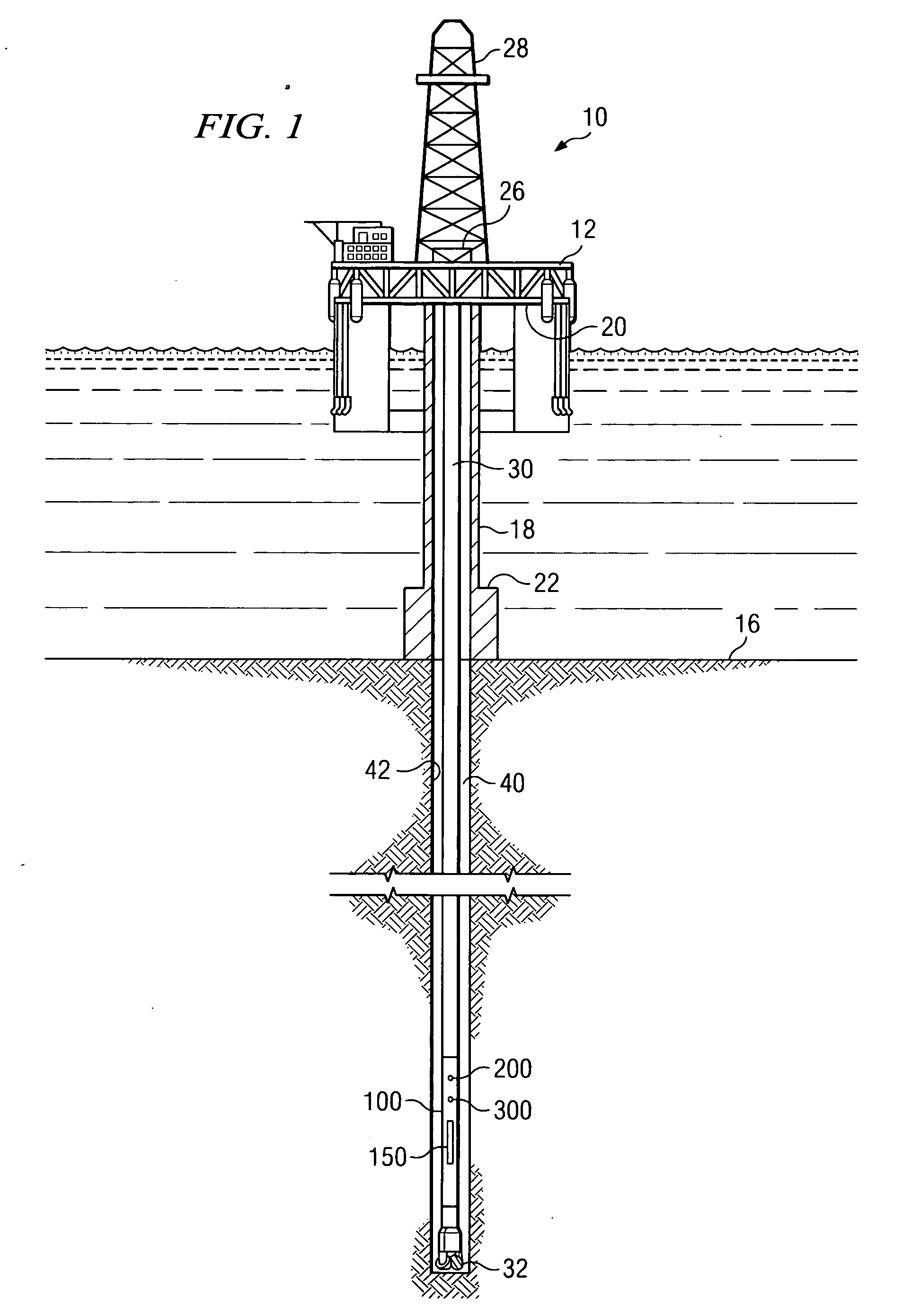
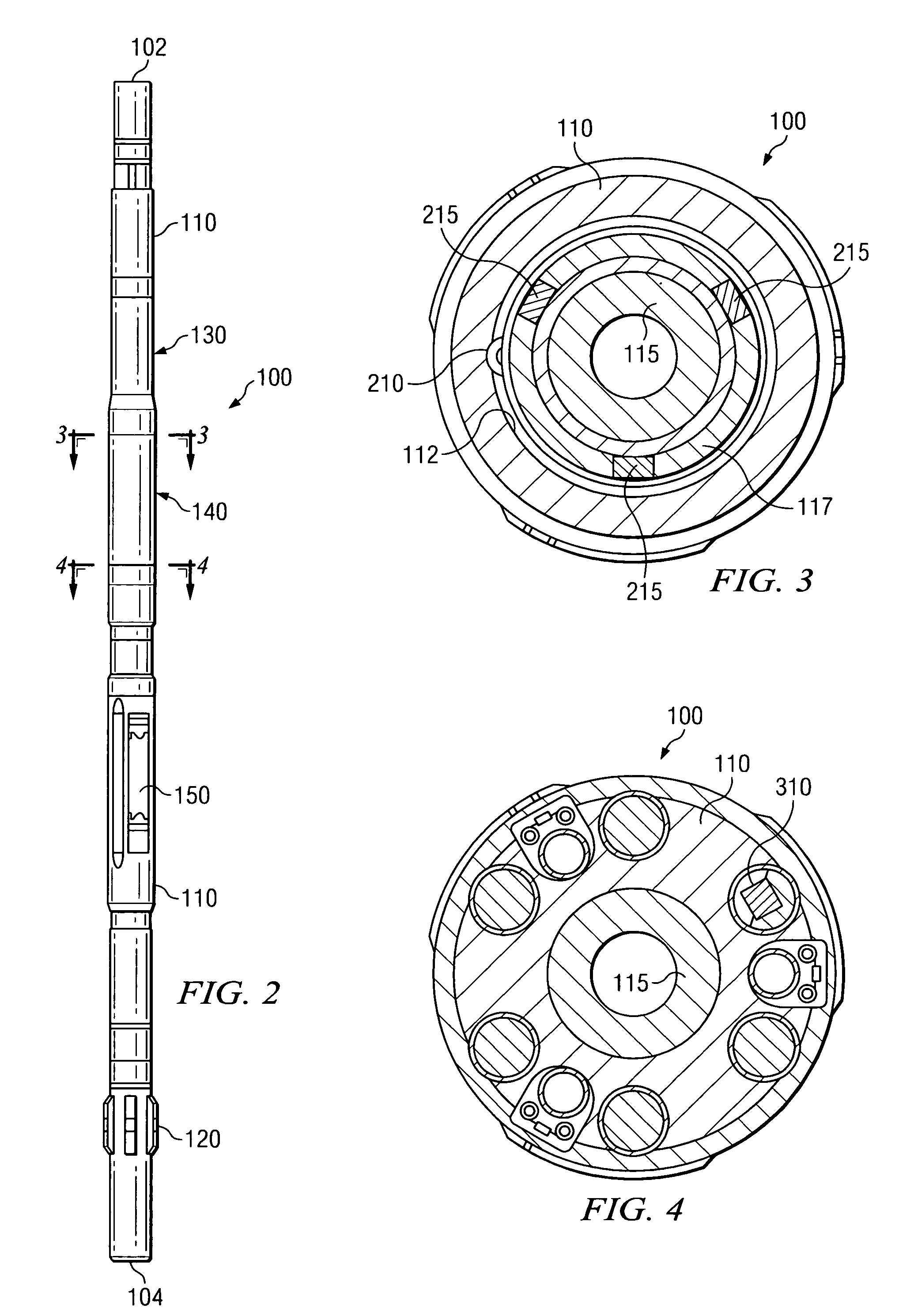
[0031]With reference now to FIG. 4, one exemplary method embodiment 400 for quantifying stick / slip downhole in accordance with the present invention is illustrated in flow chart form. A rotary steerable tool (such as that shown on FIG. 2) is deployed in a subterranean borehole at 402. As described above, the rotary steerable tool includes a shaft that rotates in a substantially non-rotating housing during drilling. At 404 the average and instantaneous rotation rates of the shaft are measured as a function of time, for example, as described below with respects to Equations 1 and 2. At 406, the measured rotation rates are processed to determine a stick / slip parameter. The stick / slip parameter may then be transmitted to the surface at 408, for example, using conventional telemetry techniques such as mud pulse telemetry.

[0032]The rotation rates of the shaft 115 may be determined at 404, for example, by counting the number of sensed pulses in a predetermined time period. This may be expr...

embodiment 500

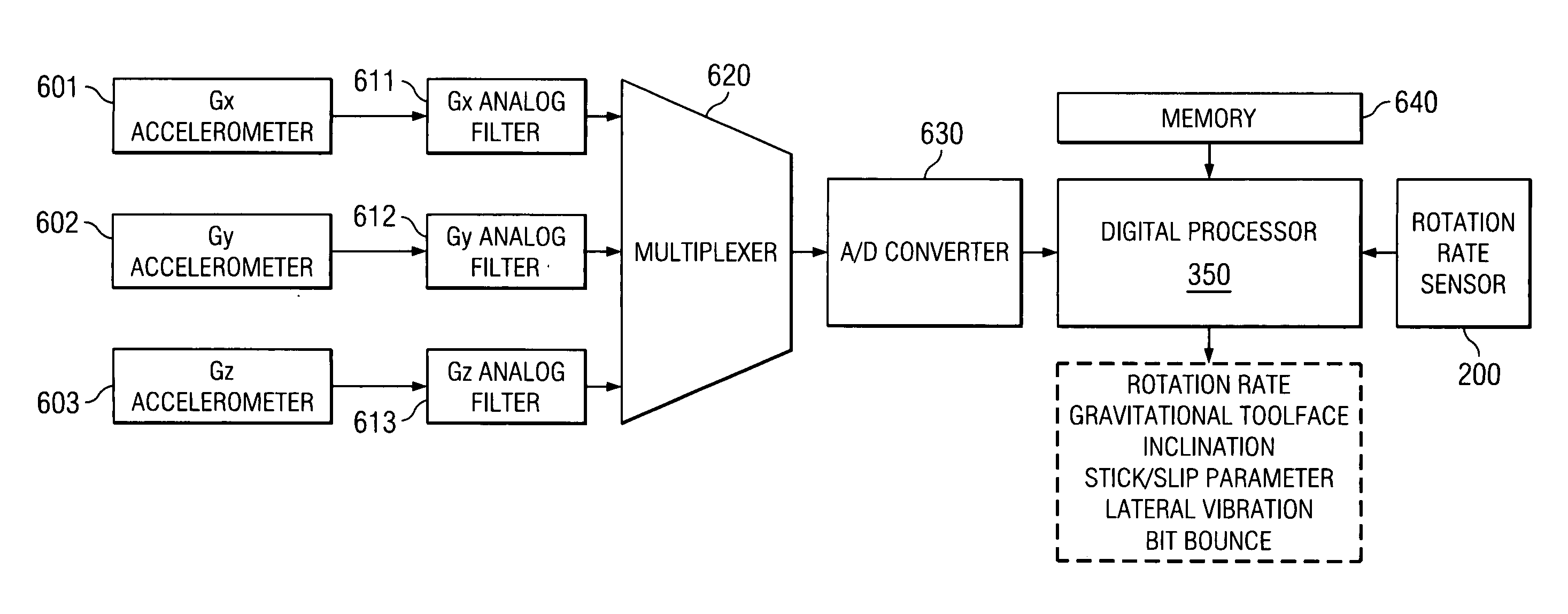
[0048]With reference now to FIG. 6, another exemplary method embodiment 500 in accordance with the present invention is illustrated in flow chart form. A rotary steerable tool (such as that shown on FIG. 2) is deployed in a subterranean borehole at 502. As described above, the rotary steerable tool includes a shaft that rotates in a substantially non-rotating housing during drilling. At 504, instantaneous and average rotation rates of the shaft may be measured as described above. At 506, the rotation rates are processed to determine a stick / slip parameter, for example, as also described above. At 508, tri-axial acceleration components of the rotary steerable tool housing 110 are measured. At 510 and 512, respectively, the tri-axial acceleration components are processed to substantially simultaneously determine inclination and tool face and axial and lateral vibration components. The stick / slip parameter and tool vibration components may then be transmitted to the surface at 514, for...


PUM


Abstract

Aspects of this invention include a rotary steerable steering tool having a sensor arrangement for measuring downhole dynamic conditions. Rotary steerable tools in accordance with this invention include a rotation rate measurement device disposed to measure a difference in rotation rates between a drive shaft and an outer, substantially non-rotating housing. A controller is configured to determine a stick/slip parameter from the rotation rate measurements. Exemplary embodiments may also optionally include a tri-axial accelerometer arrangement deployed in the housing for measuring lateral vibrations and bit bounce. Downhole measurement of stick/slip and other vibration components during drilling advantageously enables corrective measures to be implemented when dangerous dynamic conditions are encountered.

Description

RELATED APPLICATIONS[0001]None.FIELD OF THE INVENTION[0002]The present invention relates generally to downhole tools, for example, including three-dimensional rotary steerable tools (3DRS ). More particularly, embodiments of this invention relate to an apparatus and method for measuring the dynamic conditions of a rotary steerable tool, and in particular, a method and apparatus for measuring stick / slip conditions.BACKGROUND OF THE INVENTION[0003]Directional control has become increasingly important in the drilling of subterranean oil and gas wells, for example, to more fully exploit hydrocarbon reservoirs. Two-dimensional and three-dimensional rotary steerable tools are used in many drilling applications to control the direction of drilling. Such steering tools commonly include a plurality of force application members (also referred to herein as blades) that may be independently extended out from and retracted into a housing. The blades are disposed to extend outward from the housin...

Claims


Application Information

Patent Timeline
IPC IPC(8): E21B47/00
CPCE21B7/062E21B44/00E21B47/12E21B47/00E21B47/024E21B45/00
Inventor SUGIURA, JUNICHI
Owner SCHLUMBERGER TECH CORP
Why Eureka
Try Eureka