
Capacitive Position Sensor

a position sensor and capacitive technology, applied in the field of capacitive position sensors, can solve the problems of inability to meet the current generation of non-mechanical transducers, significant demand for capacitive material displacement sensors, etc., and achieve the effects of low power consumption, simple design, and high reliability

Inactive Publication Date: 2007-12-20
ATMEL CORP
View PDF23 Cites 142 Cited by
  • Summary
  • Abstract
  • Description
  • Claims
  • Application Information

AI Technical Summary

Benefits of technology

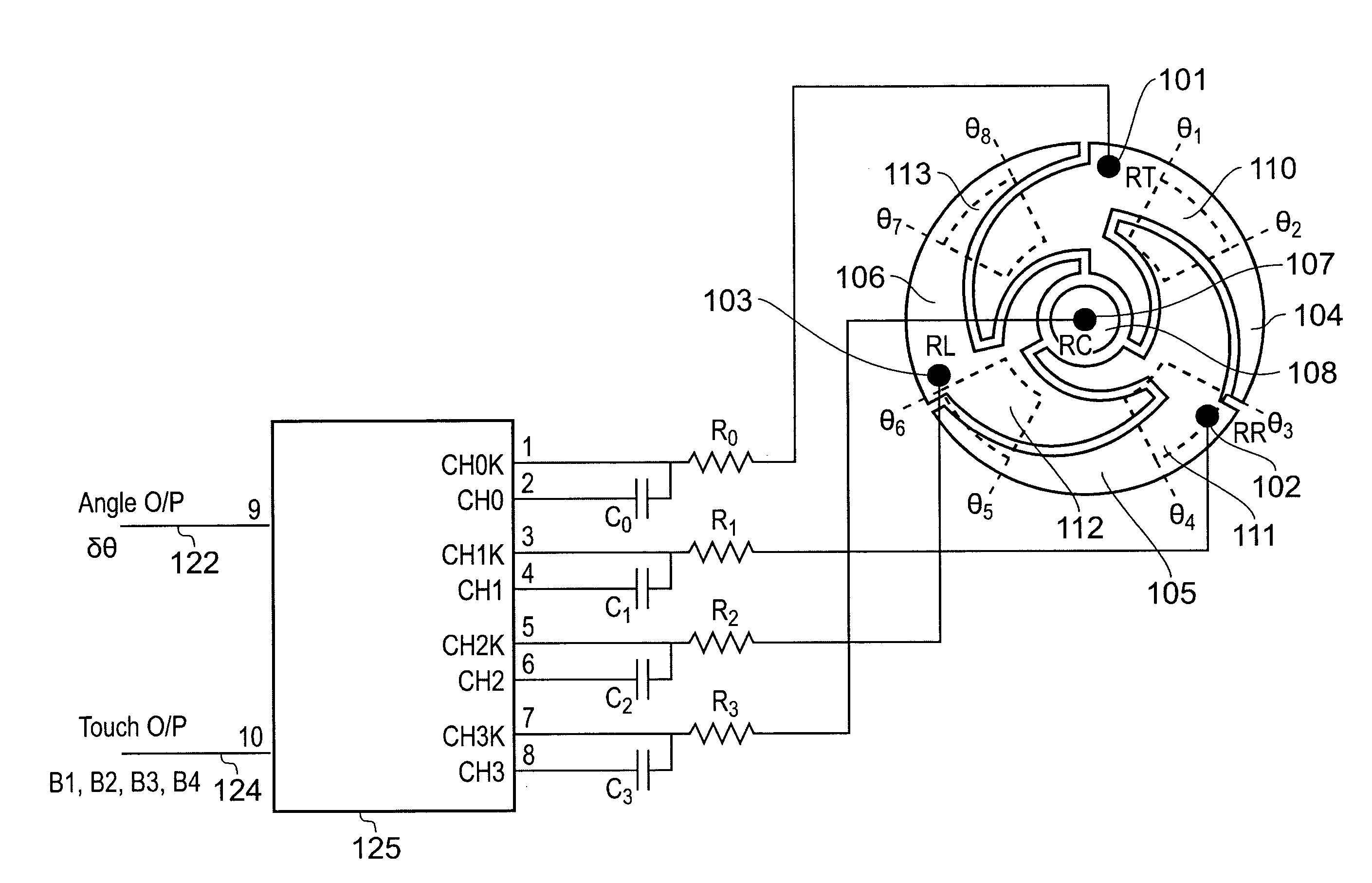
[0027] The resistive sensing element may be embodied by a single resistor, for example it may comprise a resistive material deposited on a substrate to form a continuous pattern. This provides for an easy-to-fabricate resistive sensing element which can be deposited on the substrate in any one of a range of patterns. Alternatively, the resistive sensing element may be made from a plurality of discrete resistors. The discrete resistors may be alternately connected in series with a plurality of conducting sense plates, the sense plates providing for increased capacitive coupling between the object and the resistive sensing element. This provides for a resistive sensing element which can be fabricated from widely available off-the-shelf items.
[0029] The resistive sensing element may have a substantially constant resistance per unit length. This provides for a capacitive position sensor having a simple uniform response.
[0031] The sensing channels may each include a sampling capacitor connected in series with a corresponding one of the capacitances between the terminals and the system ground such that when connected to a supply voltage each of the sampling capacitors are supplied with an amount of charge which depends on the capacitance between the corresponding ones of the terminals and the system ground. This effectively provides each sensing channel with a capacitive voltage divider comprising the capacitance of the sampling capacitor and the effective capacitance to ground caused by the object's capacitive coupling to the resistive sensing element. This allows the capacitances between each of the terminals and the system ground to be determined from the voltage measured on corresponding ones of the sampling capacitors.
[0035] To determine whether an object is present and to avoid confusion which may occur in attempting to generate a parameter indicative of a position of an object when none is present, the processor may be configured to sum the respective signals from the sensing channels and to generate a parameter indicative of a position of an object only if the magnitude of the sum exceeds a detection threshold. The threshold can be set according to how sensitive a designer wishes the capacitive position sensor to be. For example, where there are a number of closely spaced capacitive position sensors on a control panel, the designer may require a high detection threshold to prevent perceived positive detections in one capacitive position sensor when a neighbouring capacitive position sensor is being touched. In another case, a lower detection threshold may be preferred to increase the sensitivity of the capacitive position sensor. The processor may be configured to output a status signal indicative of whether the magnitude of the sum of the signals exceeds the detection threshold. This may assist appropriate responses by connected apparatus, e.g. functional equipment being controlled by a control panel.
[0040] Further objects of some embodiments of the invention are to provide for a sensor having high reliability, a sealed surface, low power consumption, simple design, ease of fabrication, and the ability to operate using off-the-shelf logic or microcontrollers.

Problems solved by technology

Similarly, there is a significant demand for capacitive material displacement sensors (e.g. fluid level sensors, mechanical movement sensors, pressure sensors etc.) at lower price points, which cannot be easily met with current generations of non-mechanical transducers.

Method used


Image

  • Capacitive Position Sensor
  • Capacitive Position Sensor
  • Capacitive Position Sensor

Examples


Embodiment Construction

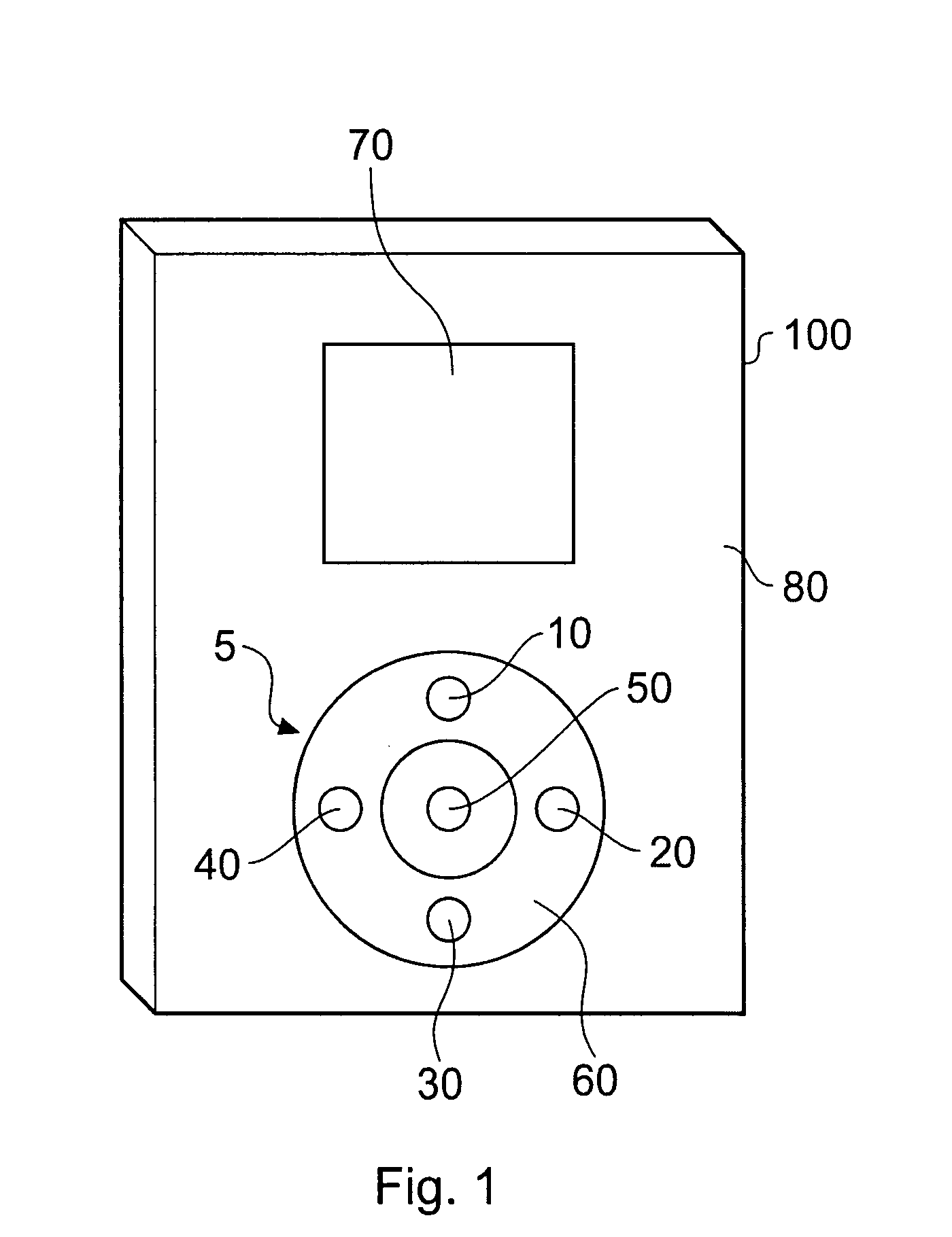
[0051]FIG. 1 illustrates an embodiment of the invention showing a mobile phone.

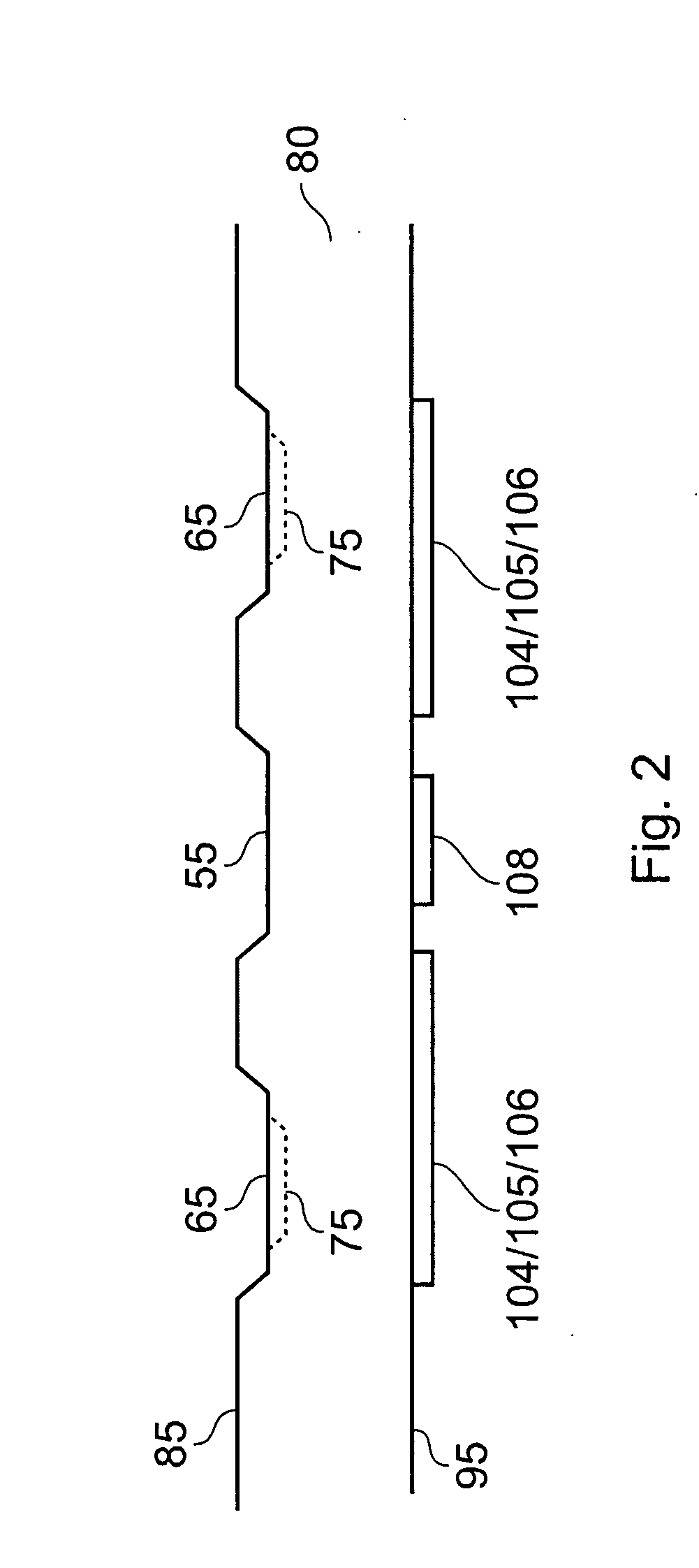
[0052] Referring to FIG. 1, there is illustrated an embodiment of the invention showing a mobile phone 100 having a multi-function sensor 5 comprising an annular sensing element 60 forming a so-called wheel, discrete sensing buttons 10, 20, 30, 40 formed within the area of the sensing element 60, and a central sensing button 50. A display 70 is also shown located above the sensor area. The display 70 and multi-function sensor 5 are formed in a front panel 80 of the device which may be made of a suitable plastics material or another material of choice such as glass, a ceramic material, a composite material, or a natural material such as wood or a wood veneer. It may also be painted.

[0053] It will be appreciated that in other embodiments the device could be a music player, radio, games console, remote controller or a device combining multiple ones of the above-mentioned functions of phone, music player, v...


PUM


Abstract

A capacitive position sensor comprising a preferably annular sensing path, the sensing path having one or more virtual buttons designated along its length. The sensing path has a plurality of terminals connected to it to subdivide it into a plurality of sections, each terminal providing a sensing channel for a signal indicative of capacitance. The sensing channels provide the signals to a processor, preferably a microcontroller, that is operable to distinguish between a user making a touch to actuate one of the virtual buttons, and a touch to perform a scrolling function. To be determined as a scroll, it is required that there is a succession of detects which span over at least a threshold distance, for example an angular or linear distance. To be determined as a touch, it is required that there is a succession of detects that all lie within one of the pre-assigned virtual button positions.

Description

BACKGROUND OF THE INVENTION [0001] The invention relates to capacitive position sensors, more particularly the invention relates to capacitive position sensors for detecting the position of an object around a curved path. [0002] Capacitive position sensors are applicable to human interfaces as well as material displacement sensing in conjunction with controls and appliances, mechanisms and machinery, and computing. [0003] Capacitive position sensors in general have recently become increasingly common and accepted in human interfaces and for machine control. In the field of home appliances for example, it is now quite common to find capacitive touch controls operable through glass or plastic panels. These sensors are increasingly typified by U.S. Pat. No. 6,452,514 which describes a matrix sensor approach employing charge-transfer principles. [0004] Due to increasing market demand for capacitive touch controls, there is an increased need for lower cost-per-function as well as greater...

Claims


Application Information

Patent Timeline
IPC IPC(8): G06F3/045
CPCG01D5/2405G06F3/044G06F3/038G06F3/03547G06F3/0447
Inventor PHILIPP, HARALD
Owner ATMEL CORP
Learn More