Rearview assemblies incorporating hands-free telephone components

a technology of hand-free telephone components and rearview mirrors, applied in the field of rearview mirrors, can solve the problems of not becoming very popular, hand-held portable cellular telephones, and vehicle audio systems without audio input jacks, and achieve the effect of preventing the exchange of certain data

Inactive Publication Date: 2007-12-20
GENTEX CORP
View PDF102 Cites 24 Cited by
  • Summary
  • Abstract
  • Description
  • Claims
  • Application Information

AI Technical Summary

Benefits of technology

[0032] According to another embodiment of the present invention, a vehicle rearview assembly provides an image of a scene to the rear of the driver of the vehicle. The rearview assembly comprises: a mounting structure for mounting to the vehicle; an audio / data transceiver associated with the mounting structure for transmitting and receiving wireless audio and data signals to / from a portable device having a similar audio / data transceiver; and a control circuit coupled to the audio / data transceiver, the control circuit being operative in a pairing mode and an operational mode, during the pairing mode, the control circuit searches for, discovers and acquires a unique identification code of a portable device with which the audio / data transceiver is to be paired, during the operational mode, the control circuit determines whether a portable device having the unique identification code is within the range of the audio / data transceiver and exchanges data with the portable device through the audio / data transceiver, also during the operational mode, the control circuit prevents the exchange of certain data with detected portable devices that are not paired with the audio / data transceiver.

Problems solved by technology

However, recent concerns have arisen that the use of handheld portable cellular telephones in a vehicle is a dangerous distraction that may cause accidents due to the need of the driver to hold onto the telephone and dial numbers and to also hold the telephone to the driver's ear rather than keeping both hands on the steering wheel.
Although hands-free telephones have been previously integrated in vehicles, they have not become very popular due in large part to the need for the driver to have a separate cellular telephone service contract with the service provider associated with the vehicle-installed telephone.
Although a driver could reduce the number of such service contracts by eliminating their portable handheld cellular telephone, most people have been reluctant to do so due to the fact that the vehicle-installed telephone cannot be removed from the vehicle and used elsewhere.
However, some vehicle audio systems do not include an audio input jack that would enable use of the speakers by the hands-free telephone system.
Further, even in vehicles that come with a standard radio having an audio input jack, there is the possibility that the vehicle owner may replace the radio with an after-market radio that does not include such an input jack.
In addition, if the hands-free telephone system is sold as an after-market system, it may be difficult to access an audio input jack on the rear of the vehicle radio and to run the appropriate wiring.
Although it may be possible to utilize an audio and data wireless connection between the vehicle's radio and the hands-free telephone system, many vehicle radios are not currently equipped with audio and data wireless transceivers.
Providing speakers in a rearview mirror assembly presents several challenges.
First, the speakers have to be relatively small and yet create an output loud enough to be clearly heard over the typical background noise present in a vehicle.
Second, the hands-free microphone, if exposed to the loudspeaker output, will become overloaded.
Even when switching is used to shut off either the speaker or the microphone, this overloading can cause problems.
Because of the distance between the user and the microphone, these microphones often detect undesirable noise in addition to the user's speech.
The noise is difficult to attenuate.
Hands-free communication systems for vehicles are particularly challenging due to the dynamically varying ambient noise that is present.
The position of the microphone relative to the person speaking will determine the level of the speech signal output by the microphone and may affect the signal-to-noise ratio.
Additionally, the microphone will typically include a wire, which, if it is mounted to the surface of the vehicle interior, will not be aesthetically pleasing.
Alternatively, if the wire is to be mounted behind the interior lining, the vehicle interior must be disassembled and then reattached so that the wire can be hidden, which may result in parts that rattle loudly or hang loosely from the vehicle frame.
Although locating the microphone in the mirror support provides the system designer with a microphone location that is known in advance and avoids the problems associated with mounting the microphone after the vehicle is manufactured, there are a number of disadvantages to such an arrangement.
Additionally, the location of the microphone on the windshield detrimentally impacts microphone design flexibility and overall noise performance of the microphone.
None of these patents, however, disclose the use of acoustic ports facing multiple directions, nor do they disclose microphone subassemblies or systems utilizing more than one microphone transducer.
The disclosed microphone subassemblies do not incorporate sufficient noise suppression components to provide output signals with relatively high signal-to-noise ratios, and do not provide a microphone having a directional sensitivity pattern or a main lobe directed forward of the housing and attenuating signals originating from the sides of the housing.
Some of the above-noted patents disclose placing the microphones in or near the seats of the driver of the vehicle while others do not specifically disclose how the microphones are mounted in the vehicle.
None of these patents, however, address the specific problems associated with mounting microphone subassemblies in a rearview mirror assembly.
However, the microphone subassembly mounted to the top of the rearview mirror assembly is more likely to be impacted by the direct laminar airflow from the windshield defroster.
Differences in aiming angle would interfere with this addition for sounds coming off axis which the array aiming ability requires.
In a horizontal microphone array, there is a direct tradeoff between reducing noise and harming desired speech coming from passengers in the vehicle.
Although the prior art microphone arrays are able to reject noise from the opposite side of the vehicle cabin, in doing so, they also reject the speech from passengers on the rejected side.
Since the spacing between the microphone transducers must be relatively small, there is a strong likelihood for overlap of noise caused by flowing air effects, particularly flowing air effects originating from the vehicle defroster.
Hands-free operation of a device used in a voice recognition system is a particularly challenging application for microphones, as the accuracy of a voice recognition system is dependent upon the quality of the electrical signal representing the user's speech.
Conventional hands-free microphones are not able to provide the consistency and predictability of microphone performance needed for such an application in a controlled environment such as an office, let alone in an uncontrolled and noisy environment such as an automobile.

Method used


Image

  • Rearview assemblies incorporating hands-free telephone components
  • Rearview assemblies incorporating hands-free telephone components
  • Rearview assemblies incorporating hands-free telephone components

Examples


fifth embodiment

[0147]FIG. 15 shows a rearview mirror assembly 10d constructed in accordance with the present invention. This embodiment differs in that it includes four microphone subassemblies, including subassemblies 140a and 140c mounted to the top of mirror housing 30 and subassemblies 140b and 140d mounted to the bottom of mirror housing 30. Such an arrangement is particularly advantageous in that it not only takes advantage of the aforementioned advantages pertaining to a vertical array of microphone transducers, but also achieves all the advantages of a horizontal array to thereby allow for more of a three-dimensional audio imaging capability. Such a capability allows the connected DSP to more readily identify desired speech based upon the position of the source of such sounds and to more readily identify and remove noise.

Internal Speakers

[0148] As mentioned above, providing speakers in a rearview mirror presents several challenges. The speakers have to be very small and yet create an out...

first embodiment

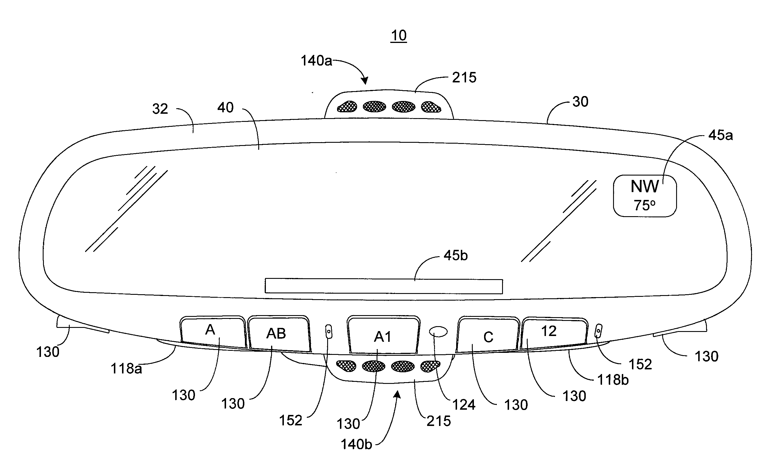
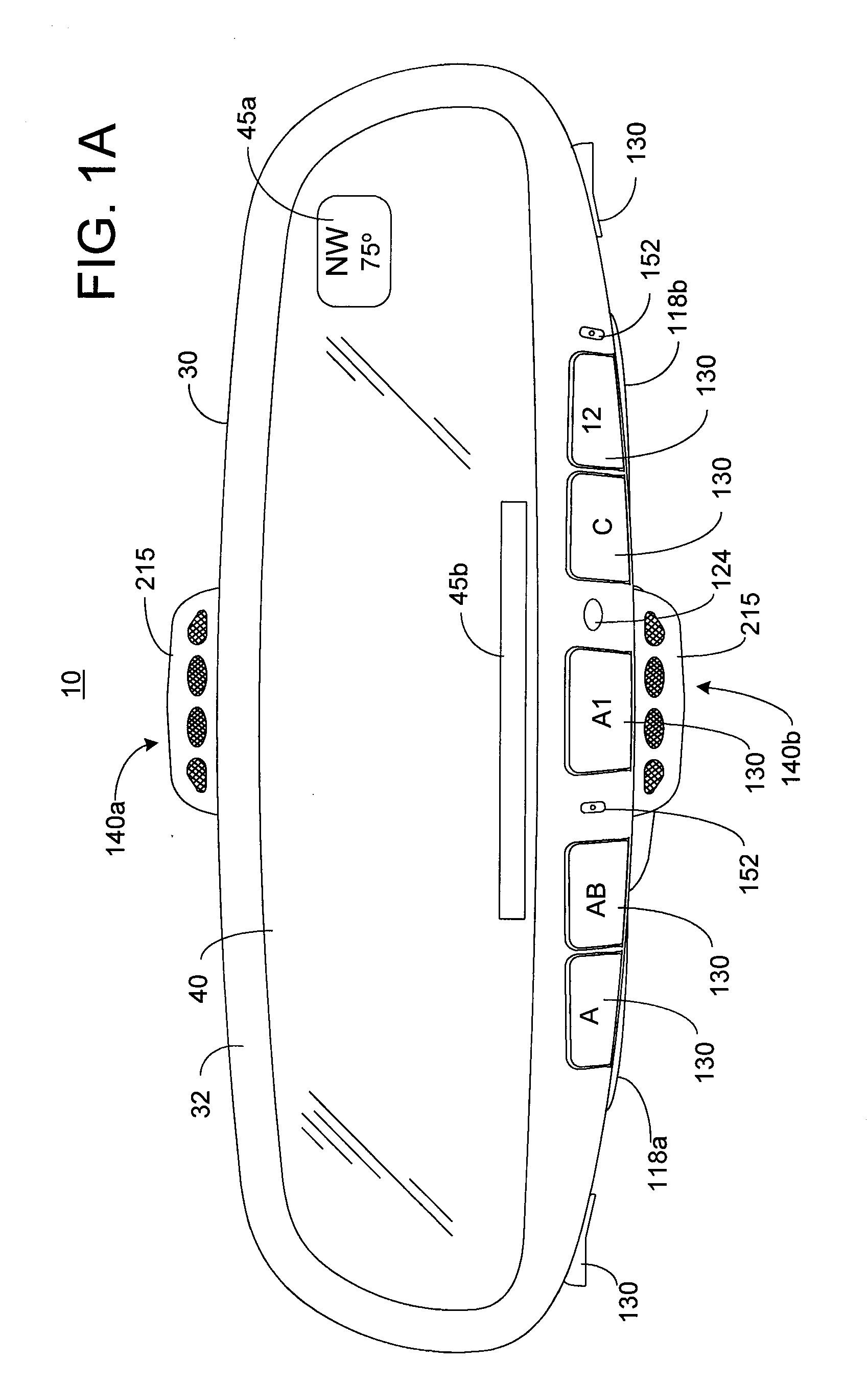
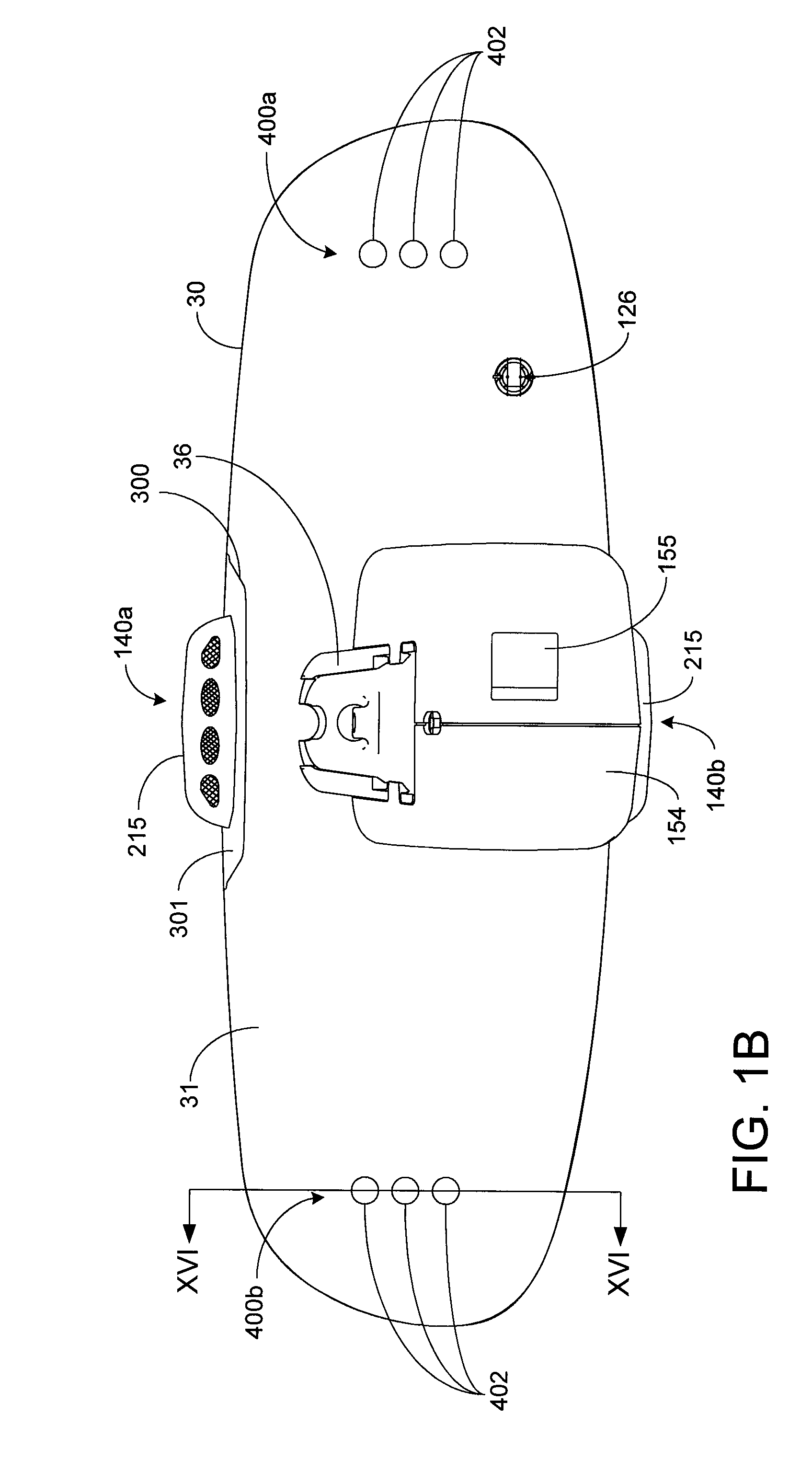
[0151] As shown in FIGS. 1A-3, in accordance with a first embodiment, two speakers 400a and 400b are mounted in the interior of the mirror housing 30 near opposite ends thereof with front ports 402 provided in mirror housing 30 to allow sound generated by the speakers to exit the mirror housing. As will be explained further below, the size and shape of ports 402 are not arbitrarily chosen, but rather are designed to cooperate with the size and shape of a front acoustic chamber 406 (FIGS. 16A and 16B) to provide a resonant frequency in the ranges noted above and thereby boost the frequency response at the most useful frequencies. Preferably, grille cloth is sealed across the opening of ports 402 and is treated with a hydrophobic material to repel water and thereby reduce the likelihood that water could penetrate through to the speakers. Preferably, the color of the grille cloth is color-matched to the color of the mirror housing as is the windscreen of the microphone subassemblies.

[0...


PUM


Abstract

The rearview assembly of the present invention may include any one or more of the following: a housing for attaching to the vehicle, the housing may define an interior space that is acoustically separated into at least two chambers; a first speaker that may be located in a first one of the at least two chambers of the interior space of the housing; a first microphone subassembly located on the top surface of the housing; a second microphone subassembly located on the bottom surface of the housing; a display positioned in the housing; an audio / data transceiver for transmitting and receiving audio and data signals to / from a portable device; and a control circuit for determining whether a portable device having a predetermined identification code is within the range of the audio / data transceiver, and for exchanging data with the portable device through the audio / data transceiver.

Description

CROSS-REFERENCE TO RELATED APPLICATIONS [0001] This application is a continuation of U.S. patent application Ser. No. 10 / 849,644, filed on May 19, 2004, now U.S. Pat. No. 7,266,204, which claims priority to U.S. Provisional Patent Application No. 60 / 471,659, filed May 19, 2003, and to U.S. Provisional Patent Application No. 60 / 536,676 filed Jan. 15, 2004, the entire disclosures of which are incorporated herein by reference. [0002] This application is also a continuation-in-part of U.S. patent application Ser. No. 11 / 315,866, filed on Dec. 22, 2005, which is a divisional of U.S. patent application Ser. No. 09 / 827,304, filed on Apr. 5, 2001, now U.S. Pat. No. 6,980,092, which claims priority under 35 U.S.C. §119(e) on: U.S. Provisional Application No. 60 / 242,465, filed on Oct. 23, 2000; U.S. Provisional Application No. 60 / 216,297, filed on Jul. 6, 2000; and U.S. Provisional Application No. 60 / 195,509, filed on Apr. 6, 2000.BACKGROUND OF THE INVENTION [0003] The present invention gener...

Claims


Application Information

Patent Timeline
Patent Type & Authority Applications(United States)
IPC IPC(8): G02B7/182B60RB60R1/12H04M1/60
CPCB60R1/12H04M1/6091G02B7/182B60R2001/1284B60R1/04
Inventor WATSON, ALAN R.BRYSON, MICHAEL A.
Owner GENTEX CORP
Why Eureka
Try Eureka