Cooling Structure For Secondary Battery

Inactive Publication Date: 2007-12-20
TOYOTA JIDOSHA KK
View PDF3 Cites 36 Cited by
  • Summary
  • Abstract
  • Description
  • Claims
  • Application Information

AI Technical Summary

Benefits of technology

[0014] In accordance with the cooling structure for a secondary battery of the present invention, provision of the exhaust duct between the bottommost face of the battery pack and the vehicle floor allows the exhau

Problems solved by technology

However, there is a problem when a battery of large capacitance is to be loaded in the vehicle.
A large battery pack cannot be placed under the seat since the space is insufficient.
Further, the large amount of air to cool the battery pack may cause discomfort to the passenger if the cooling air subsequent to the cooling operation is simply output from one place (in the vehicle), leading to degradation in the in-car environment.
However, this publication is silent about the specific structure of disposing the cooling apparatus to cool the battery pack and other peripheral equipment.
However, the

Method used


Image

  • Cooling Structure For Secondary Battery
  • Cooling Structure For Secondary Battery
  • Cooling Structure For Secondary Battery

Examples


Embodiment Construction

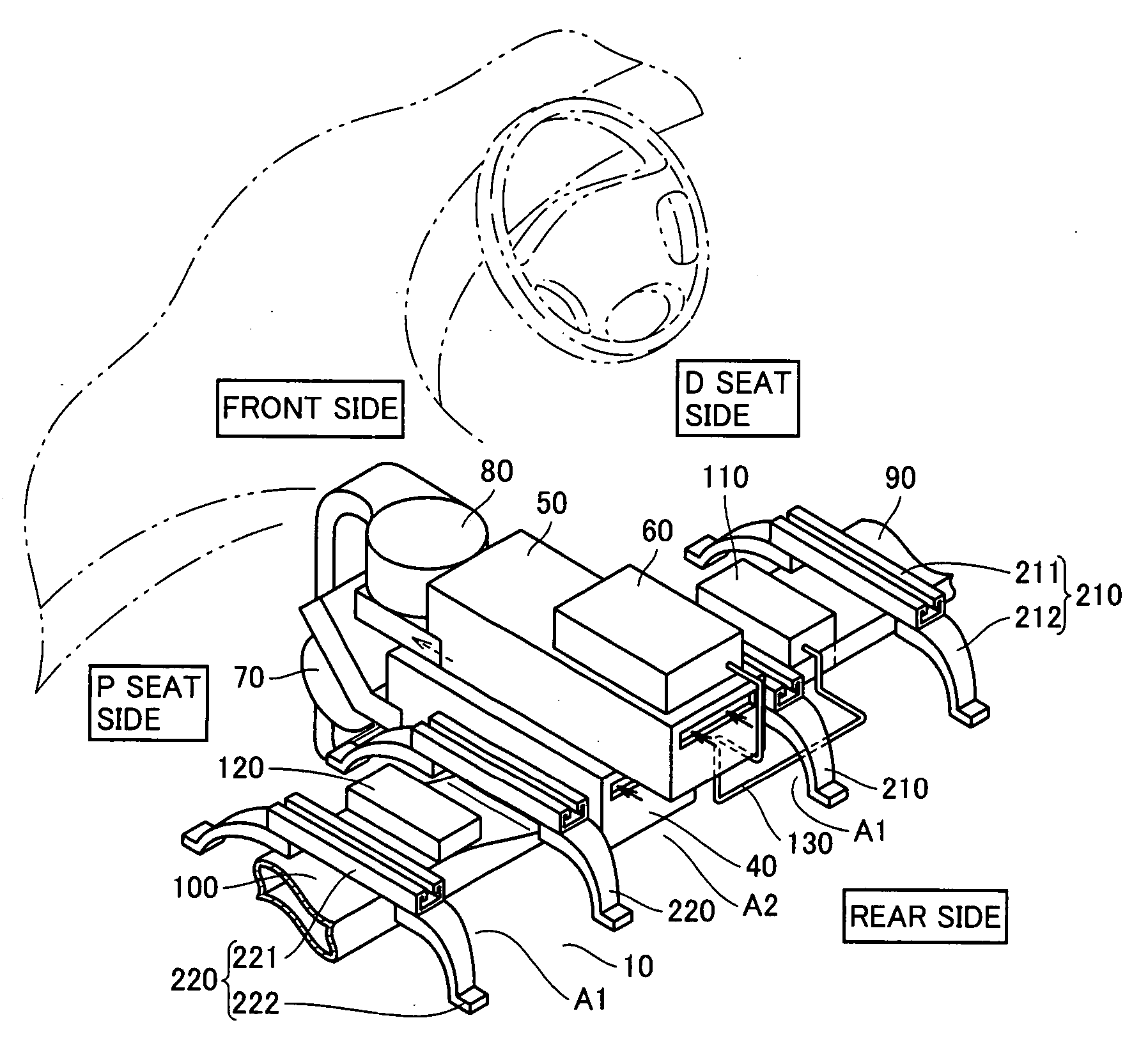
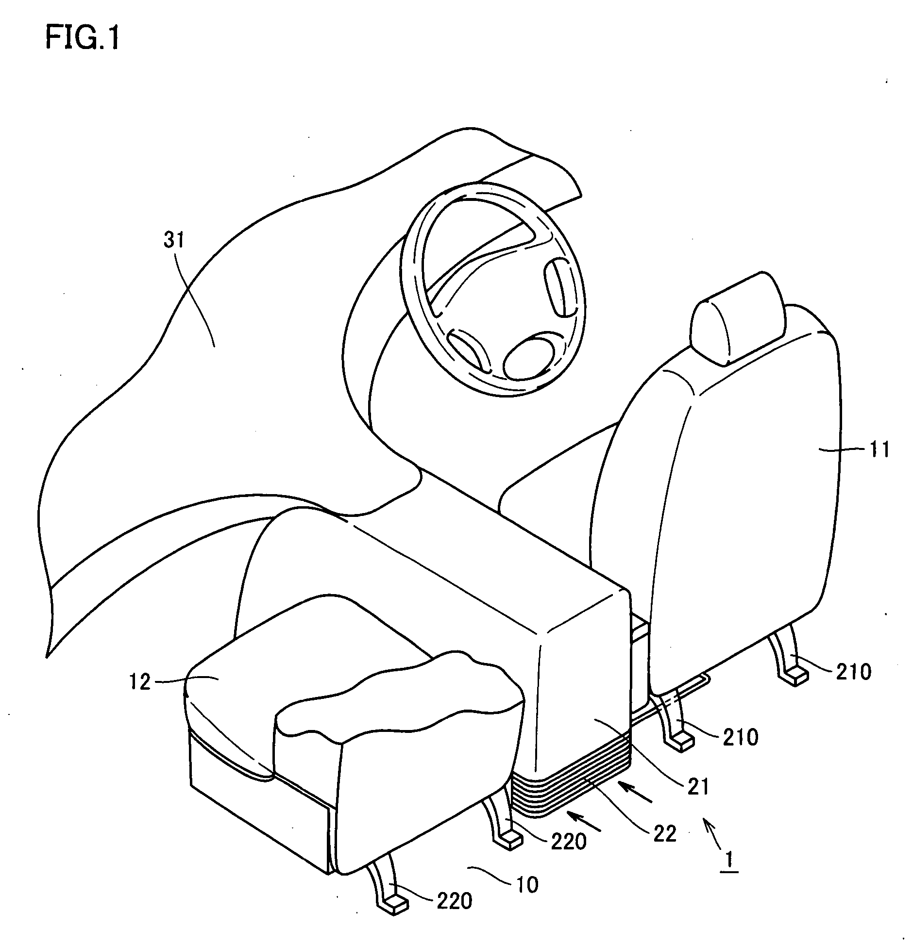
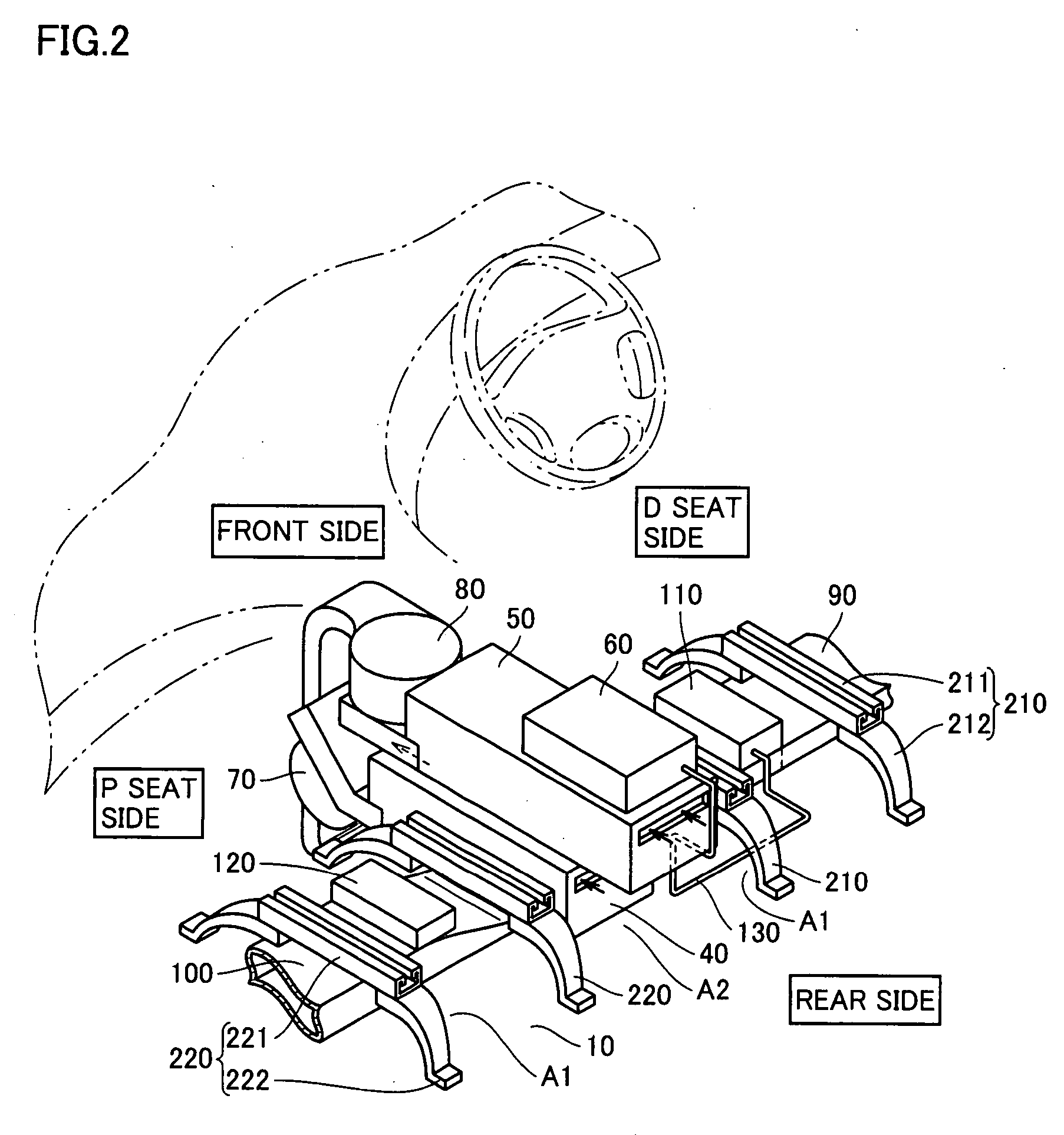
[0023] An embodiment of a battery pack loaded in a vehicle according to the present invention will be described hereinafter with reference to the drawings. In respective drawings, the fore side, the aft side, the driver seat side, and the front passenger seat side of the vehicle are represented as the “front side”, “rear side”, “D side” and “P side”, respectively. First, the schematic structure in the passenger compartment of the vehicle will be described with reference to FIGS. 1 and 2. FIG. 1 is a partial perspective view of an appearance in the passenger compartment of a vehicle, and FIG. 2 is a partial perspective view in the passenger compartment of the vehicle with the front seat and center console box removed.

[0024] (Passenger Compartment of Vehicle)

[0025] Referring to FIG. 1, a passenger compartment 1 of a vehicle includes, at the front region of the vehicle, a dash board 31 in addition to a driver seat 11 and a front passenger seat 12 arranged as the front seat. Driver se...


PUM


Abstract

The cooling structure for a secondary battery has a first center exhaust duct and a second center exhaust duct arranged on a floor between the driver seat and the front passenger seat. Each exhaust duct is located between the bottommost face of the first battery pack and the vehicle floor to constitute a heat insulation layer. By employing this configuration, there can be provided a cooling structure for a secondary battery that is not affected by heat from an exhaust pipe located under the floor, even in the case where a battery pack is arranged between the driver seat and the front passenger seat.

Description

TECHNICAL FIELD [0001] The present invention relates to a cooling structure for a secondary battery loaded in an electric vehicle and the like. BACKGROUND ART [0002] In recent years, electric vehicles that employ an electric motor as the driving source and also the so-called hybrid vehicles based on the combination of an electric motor as the driving source and another driving source (for example, an internal combustion engine, fuel cell, or the like) are adapted to practical use. In such vehicles, a battery to supply electricity qualified as the energy to the electric motor is loaded. For this battery, a secondary battery represented by a nickel-cadmium battery, a nickel-hydrogen battery, a lithium ion battery, or the like that can be charged and discharged repeatedly is used. [0003] A secondary battery is constituted of a battery module in which battery cells are stacked. This battery module is loaded in a vehicle in a stored state in a battery case. This battery case and the batt...

Claims


Application Information

Patent Timeline
IPC IPC(8): H01M10/50B60K1/04B60K11/04B60K11/06H01M50/204H01M50/249
CPCB60K1/04B60K2001/005B60L11/1874B60L11/1877B60L11/1879B60L2240/36Y02T10/705H01M10/5004H01M10/5016H01M10/5063H01M10/5095Y02T10/7005H01M2/1072H01M10/625H01M10/663H01M10/6561H01M10/613B60L58/26B60L50/66B60L50/64Y02T10/70Y02E60/10H01M50/204H01M50/249
Inventor TSUCHIYA, TAKENORI
Owner TOYOTA JIDOSHA KK
Why Eureka
Try Eureka