Plate-fin heat exchanger

Inactive Publication Date: 2007-12-27
PRAXAIR TECH INC
View PDF7 Cites 20 Cited by
  • Summary
  • Abstract
  • Description
  • Claims
  • Application Information

AI Technical Summary

Benefits of technology

[0010]Since the cross-sectional flow area is now increased, greater fin density can be employed than a plate-fin heat exchanger of the present invention to obtain the same pressure drop as that of a prior art plate-fin heat exchanger of similar size, namely, one having the same length, width and height while also possessing a greater heat transfer capacity due to the increase in fin density. Alternatively, a heat exchanger of the present invention could be designed to be m

Problems solved by technology

Heat exchanger efficiency design is limited by the fact that each heat exchanger must be formed from individually brazed cores, which are in turn constrained in maximum cross-sectional flow areas because the brazing ovens are limited in size.
Consequently, the size and the design of a plate-fin heat exchanger is limited by the size of the furnace.
The increase in surface area inevitably comes at the expense of more frictional pressure drop.
All of these designs will provide higher rates of heat transfer at the expense of increased pressure drop.
While the degree of increase in compression that may be required to o

Method used


Image

  • Plate-fin heat exchanger
  • Plate-fin heat exchanger
  • Plate-fin heat exchanger

Examples


Embodiment Construction

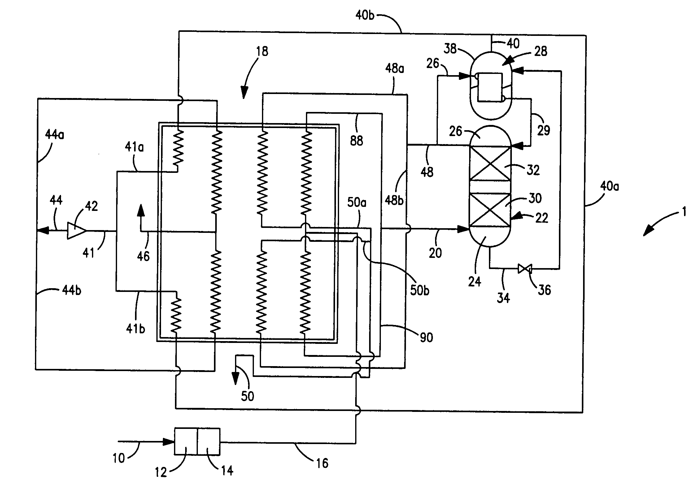
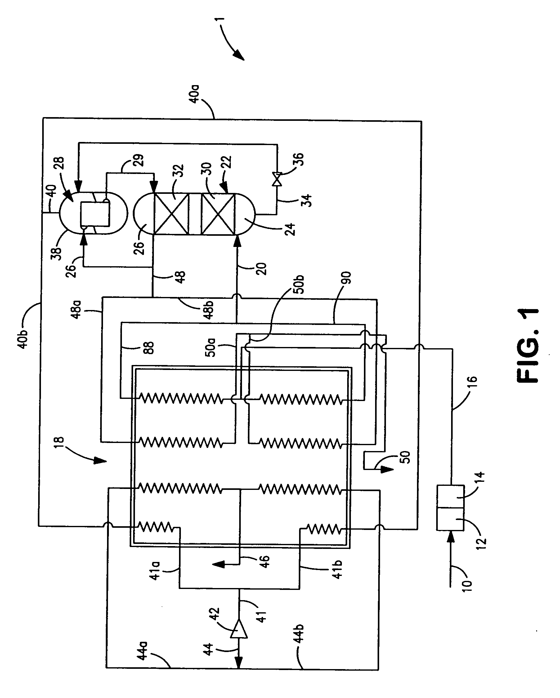
[0021]With reference to FIG. 1 an air separation plant 1 is illustrated that is used to generate nitrogen. Such an air separation plant is known as a nitrogen generator.

[0022]A feed air stream 10 is compressed at a compression unit 12 that may be a multistage compressor having inter-stage cooling between stages. The compressed and purified air stream is then introduced into a purification unit 14 that is well known in the art. Prepurification unit 14 that can be a temperature swing adsorption unit having beds of alumina or molecular sieve type adsorbent operating out of phase to remove the lower boiling components of the air such as water and carbon dioxide. The resultant compressed and purified stream 16 is cooled to at or near its dew point in main heat exchanger 18 and introduced as a compressed, purified and cooled stream 20 into a distillation column 22.

[0023]The introduction of compressed, purified and cooled air stream 20 into distillation column 22 initiates the formation of...


PUM


Abstract

A plate-fin heat exchanger having a plurality of layers for indirectly exchanging heat between two or more fluids. The heat exchanger is provided with two sections and inlets and outlets to the sections to cause streams of the fluids to flow within the two sections parallel to the length of the heat exchanger between central locations and the ends of the heat exchanger. In such manner, the cross-sectional flow area of such a heat exchanger is greater than the heat exchanger in which the flow is from one end to the other end of the heat exchanger. This increase in cross-sectional flow area reduces the pressure drop within the heat exchanger.

Description

FIELD OF THE INVENTION[0001]The present invention relates to a plate-fin heat exchanger having a plurality of layers made up of plates and fins for indirectly exchanging heat between fluids flowing within the layers. More particularly, the present invention relates to such a plate-fin heat exchanger in which the layers are divided into two lengthwise extending sections so that streams of the fluids to be subjected to indirect heat exchange flow through both of the sections to increase the cross-sectional flow area within a layer.BACKGROUND OF THE INVENTION[0002]Plate-fin heat exchangers have particular applications in cryogenic plants that are used in natural gas processing and an air separation. Such heat exchangers are typically fabricated by fusing layers of aluminum flow passages having interior fining within a vacuum brazing oven. In a typical brazing operation, fins, parting sheets and end bars are stacked to form a core matrix. The core matrix is placed in the vacuum brazing ...

Claims


Application Information

Patent Timeline
IPC IPC(8): F28F3/08F25J3/00
CPCF25J3/04218F25J3/04284F25J3/044F25J3/04872F28F3/02F25J2290/40F25J2290/42F28D9/0037F25J5/002F28F2250/104
Inventor HOWARD, HENRY EDWARDJIBB, RICHARD JOHN
Owner PRAXAIR TECH INC
Why Eureka
Try Eureka