Method and apparatus for dynamic space-time imaging system

a dynamic space-time imaging and apparatus technology, applied in the field of dynamic space-time imaging systems, can solve the problems of difficult to achieve stereoscopic profiling with accurate detailed measurements of three-dimensional objects, involving a quite expensive apparatus, and finite (and relatively long) time for all points to be illuminated and surveyed

Inactive Publication Date: 2007-12-27
4D IMAGING +1
View PDF4 Cites 118 Cited by
  • Summary
  • Abstract
  • Description
  • Claims
  • Application Information

AI Technical Summary

Benefits of technology

[0012] The present invention utilizes a method for dimensional measurement of the surface contours of an object. The method employs selective computer controlled projection of a variety of patterns onto the object, and imaging of the patterns as they fall on the object to encode the topographic features of the object by analyzing how the images of the patterns projected onto the surface contours of the object cause the imaged pattern to diverge from the projected pattern. The object can have a motional variation such as a breathing human, a complex flexing civil or mechanical structure, or a stress-strain testing of an airplane, vehicle, beam, bridge, or other structure. In the present description even faster motions can be accommodated with no blurring. Such motions could be associated with spinning wheels or walking patients. The images of the object are collected by a digital camera, and are processed in a computer program in a manner such that a complete three dimensional map of the surface of the object is obtained in digital form. In order to facilitate precision, the system may generate a digital pattern which is projected onto the object in a manner so that the pattern configuration provides the data for a computer program to determine exact dimensions. The system may also use a laser source of radiation by scanning the object rapidly using a laser beam. By utilizing a rapid procedure and reiterating it, the data provides a measure of the time variations of the size of the object. The usual output of the digital system supplies a three dimensional true color image as well as exact dimensional data on the depth, width, height and contours of the surface of the object. In one configuration, a pattern of colored lines is projected onto the object and all of the data for the 3 D view is obtained in a single camera shot. Advantages of the single shot are: 1) fast enough to eliminate mechanical motion effects of the object; 2) minimizes heat; 3) can obtain 3-d images in outdoor lighting; 4) projector and camera combination are light enough to be portable. In another configuration the projector illuminates continuously, and the motion of the object can be studied by measuring differences from an initial 3d image.
[0015] The invention is also useful for identification and recognition for security applications, as it can provide motion detection and trigger three dimensional mapping of an intruded area. Also it is very applicable to accident analyses and prediction of mechanical failure where dimensional changes in mechanical structures may be analyzed in three dimensions. The invention is also very useful in imaging the holds of ships, planes, freight trains, and warehouses, where the images may yield numerical values for the exact amount and distribution of space available for use, or when partially loaded, for a determination of the space available for further use. Another application is for security in examining the cargo space in ships, trucks, planes, and other compartments; i.e., by determining the volume numerically exactly so that the existence of hidden compartments can be found. Another application is to microscopy. Here the three dimensional sizes of the object, (for example, a microbe), are readily determined, and the mobility of the microbe may be measured. Recent research also indicates that weaponized microbes in a cloud can be identified by the reflected light spectrum and by the change in shape of a cloud. This invention provides a significant ad vantage over the usual two dimensional measurements used for microscopic analyzes.

Problems solved by technology

In contrast, the development of stereoscopic profiling with accurate detailed measurements of three dimensional objects has been difficult to achieve.
While such systems provide good three dimensional data, they involve a quite costly apparatus because the time of flight must be measured to a few picoseconds, and the mirrors used to direct the laser beam as well as the mirrors used to route the reflected beam must be exact to a small division of a minute of arc.
In addition, the scanning of a three dimensional object with a laser beam requires a considerable length of time, due to the fact that each incremental point on the surface of an object must be illuminated by the beam and the time of flight measured, resulting in a finite (and relatively long) time for all points to be illuminated and surveyed.
The use of such relatively static methods does not provide for the real-time measurement of dynamic details needed for dynamically imaging and measuring surface contour dimensions of objects which have movement, such as a bridge or beam undergoing stresses and strains.

Method used


Image

  • Method and apparatus for dynamic space-time imaging system
  • Method and apparatus for dynamic space-time imaging system
  • Method and apparatus for dynamic space-time imaging system

Examples


Embodiment Construction

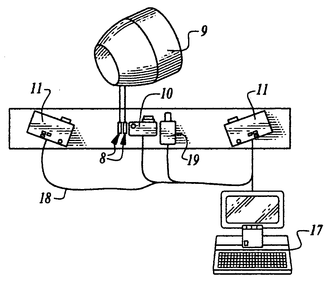
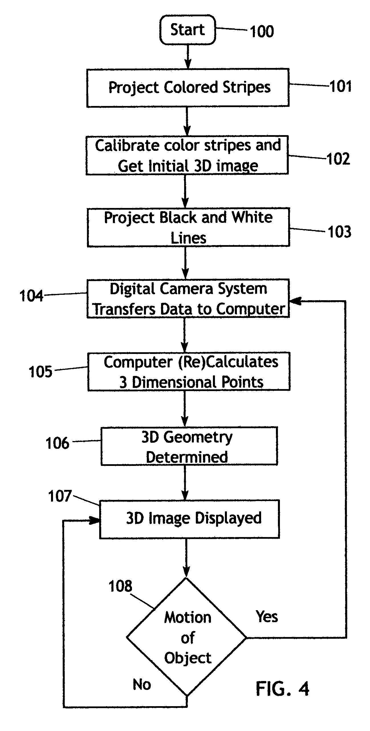
[0032] The present invention generally comprises a method for generating a three dimensional map of the surface of an object, and analyzing the dimensional data to examine the object in useful ways. Referring to FIG. 1, the method involves providing a pair of projectors 11, each of the projectors directed to project a pattern of colored lines on an object 9. A single flash projector may be composed of a flash lamp and a patterned source or a digital projector. The flash lamp provides high intensity light for a short time. This has two advantages: it allows the fast study of mechanical position without image blurring and it avoids heating the object while still providing enough light to illuminate the object. The projectors are separated and spaced to illuminate differing aspects of the object. A digital camera 10 is directed at the object 9 to acquire images of the object, and the configuration of the projected patterns of colored (or black and white) lines on the surface of the obj...


PUM


Abstract

A method for creating a 3 D map of the surface contours of an object includes projecting a variety of patterns onto the object, and imaging the patterns as they fall on the object to encode the topographic features of the object. In one embodiment a three dimensional image is taken in a single flash to avoid blurring due to motion of the object. Thereafter a secondary pattern is projected to detect changes in the initial image. The images are processed in a computer program in a manner such that a complete 3D map of the surface of the object is obtained in digital form. Reiteration of the method can detect motional variation such as a breathing human, flexure of a complex mechanical structure, or a stress-strain testing of an airplane, vehicle, beam, bridge, or other structure.

Description

CROSS-REFERENCE TO RELATED APPLICATIONS [0001] This application is a continuation-in-part of application Ser. No. 10 / 966,095, filed Oct. 14, 2004, for which priority is claimed.FEDERALLY SPONSORED RESEARCH [0002] Not applicable. SEQUENCE LISTING, ETC ON CD [0003] Not applicable. BACKGROUND OF THE INVENTION [0004] 1. Field of the Invention [0005] The present invention relates to an apparatus and method for producing a rapid time-related three dimensional image with a numerical profile of an object. More particularly, it involves projecting complex digitally based patterns of electromagnetic waves (e.g. light) or scanning laser beams(s) on to the object, photographing these patterns with a fast response digital camera, and rapidly calculating a dimensional map of the contours, edges, and openings of the object. In a previous patent application, Ser. No. 10 / 966,095, filed Oct. 14, 2004 we described the general technique for carrying out the method. In this patent we extend this general...

Claims


Application Information

Patent Timeline
Patent Type & Authority Applications(United States)
IPC IPC(8): A61B6/03
CPCA61B5/0064A61B5/0077A61B5/113A61B5/1176H04N13/0253G01S17/88G01S17/89G06T7/0057H04N13/0207G01N21/8806G06T7/521H04N13/207H04N13/254
Inventor STEVICK, GLEN R.RONDINONE, DAVID M.SINGER, JEROME R.SAGLE, ALLAN L.
Owner 4D IMAGING
Why Eureka
Try Eureka