Load bearing textile clamp

a textile clamp and load bearing technology, applied in the direction of snap fasteners, draperies, buckles, etc., can solve the problems of inability of sails to transfer potential wind energy into force, the range of applications of industrial textiles up to the development of modern synthetic materials was self-limiting, and the textiles of natural fibers quickly became impractical. achieve the effect of increasing load and increasing load transfer efficiency

Inactive Publication Date: 2008-01-03
MURRAY MICHAEL EDWARD
View PDF8 Cites 31 Cited by
  • Summary
  • Abstract
  • Description
  • Claims
  • Application Information

AI Technical Summary

Benefits of technology

[0009] The invention enables textiles to bear greater loads by increasing the efficiency of load transfer from fibers to a secondary structure. It is remo

Problems solved by technology

Two principle factors limited the ability of a sail to transfer the potential wind energy into a force to drive a vessel: the first being the strength of the cloth; the second being the method used to reinforce the edge and affix the sailcloth to the support structure.
The range of applications for industrial textiles up to the development of modern synthetic materials was self limiting.
Textiles of natural fibers quickly became impractical for many high load applications which naturally limited the development of additional uses and methods of attachment.
While these current methods of sewn or welded hems to reinforce edges using straps or grommets to transfer loads are generally successful in moderate load applications, they do not perform as well as possible under high loads.
This places a greater strain on the fibers directly in line with the grommet or strap making these fibers vulnerable to failure.
Additionally, distortion occurs along the border edges as the few fibers aligned with the anchor points bear the greatest percentage of the load.
Compounding failures occur across the reinforced edge as the highly tensioned fibers break, causing shock loads to the remaining fibers which cause them to break as well.
Another family of current art uses better load distribution along the edge of the load bearing textile, but still falls short of maximizing the textile strength because the reinforcement method still relies on stitching.
While these products have less likelihood of failure at the attachment point and le

Method used


Image

  • Load bearing textile clamp
  • Load bearing textile clamp
  • Load bearing textile clamp

Examples


Embodiment Construction

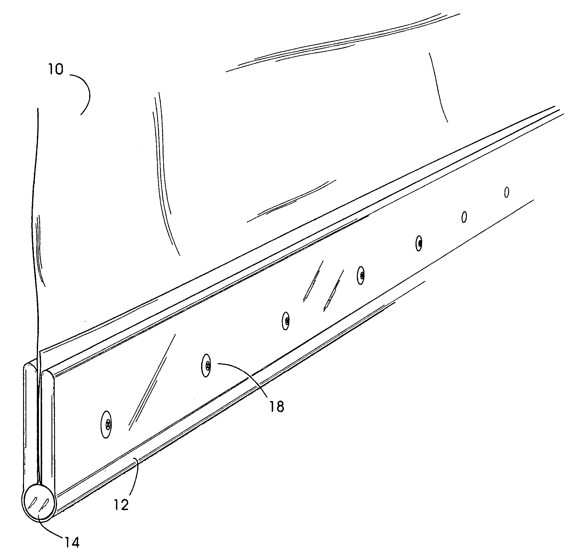
[0034] This invention describes an intermediary device between a load-bearing textile and a secondary structure which secures the textile in a manner to transfer loads from the textile into an anchor in a fast, cost effective, and strong field assembled clamp that retains much of the strength of the textile and resists load induced deformation from point loading and environmental degradation. The invention replaces the typical and laborious task of gluing and / or sewing reinforcements and / or affixing grommets and / or plates into textiles so that they may carry high loads.

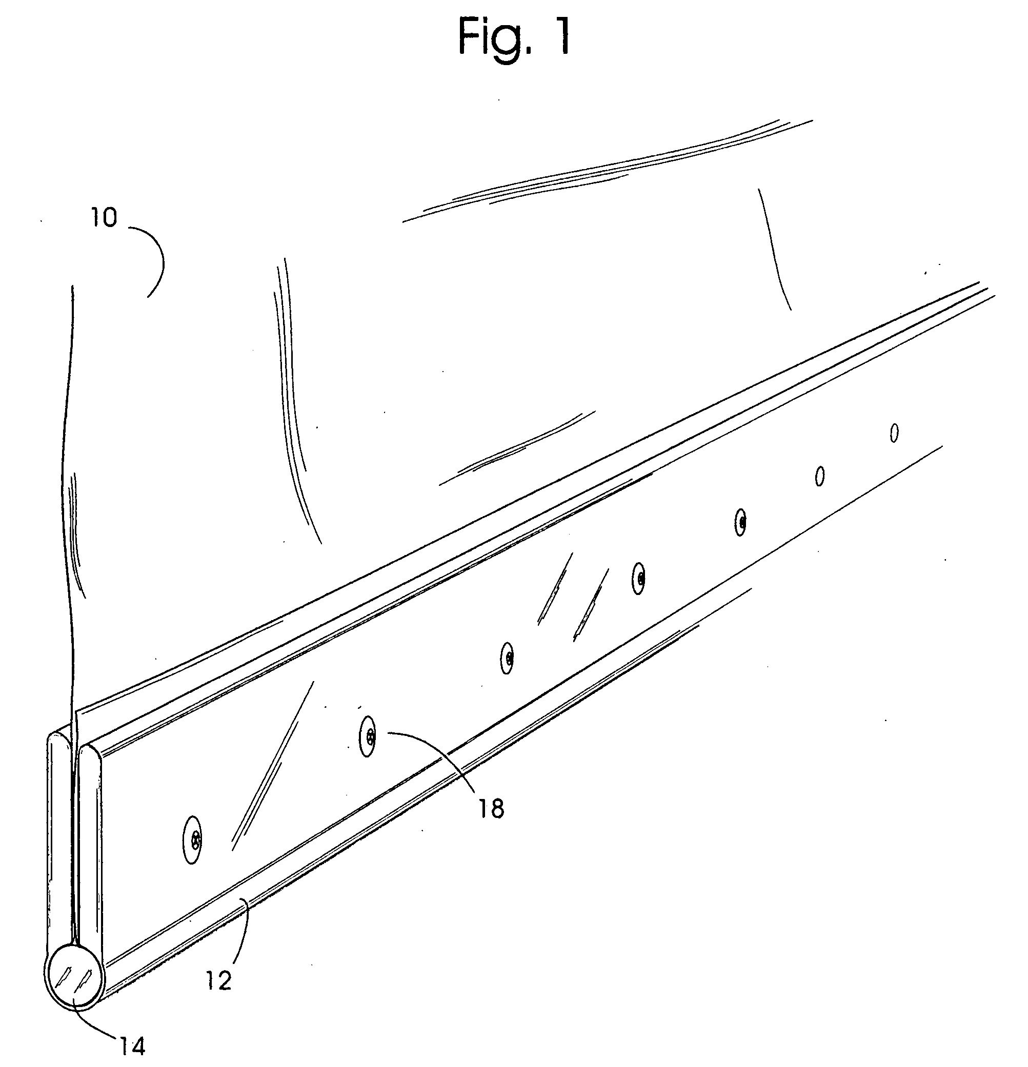
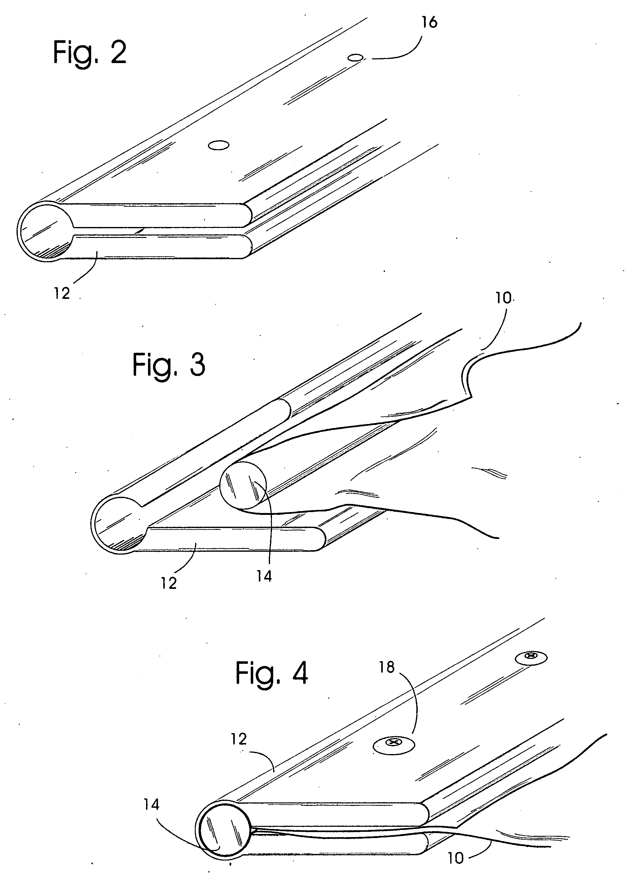
[0035] These goals are achieved by the invention by incorporating at the edge of the textile panel a round turn around a length of rod inside a corresponding length of an essentially U-shaped sleeve that forms a compressive clamp around the assembly. To apply the clamp to a textile panel, the edge of the textile is folded once around the rod with sufficient overlap, and then the rod and textile are inserted into the ...


PUM


Abstract

An invention where a removable load bearing textile clamp comprised of an outer compressive sleeve configured to accept an internally positioned removable rod such that a textile can be led around the rod and positioned inside the compressive sleeve and said sleeve once fastened can form a clamp assembly between the sleeve, rod, and textile to create a load bearing textile clamp that can be attached to a secondary structure such that the fiber strength of the textile is retained and the textile panel can perform work.

Description

FIELD OF THE INVENTION [0001] This invention relates to methods of reinforcing and attaching the edges of a textile panel such that they are able to convey loads into a secondary structure such that the load is resisted, energy is transferred, and the panel does work. Primarily, load bearing articles made of textiles are designed to work in tension, where the strength and orientation of fibers is a determining factor in how the article is used and the methods used to transition loads into a secondary structure is a determining factor in the load bearing capacity of the device. Articles such as lifting devices, tension structures and protective barriers such as blast screens and hurricane shutters are examples of products where the tensile strength and lightweight properties of modern textiles have been used to create new products. BACKGROUND OF THE INVENTION [0002] For millennia, man has used woven textile goods for a variety of domestic and industrial applications. To enable woven ...

Claims


Application Information

Patent Timeline
IPC IPC(8): A44B21/00A44B99/00
CPCA47H23/01Y10T24/44043E04H15/646
Inventor MURRAY, MICHAEL EDWARD
Owner MURRAY MICHAEL EDWARD
Why Eureka
Try Eureka