
Oxygen injection method

Inactive Publication Date: 2008-01-03
PRAXAIR TECH INC
View PDF22 Cites 14 Cited by
  • Summary
  • Abstract
  • Description
  • Claims
  • Application Information

AI Technical Summary

Benefits of technology

[0016]Ignition and combustion of the fuel while within the passageway is prevented by not introducing an ignition source and providing the passageway with an inner surface uninterrupted by any discontinuity within which the outer circumferential region could otherwise decelerate and provide a site for stable combustion of the fuel.
[0017]A flame envelope is produced that surrounds a jet of oxygen formed from the inner central region of the structured jet and that initially has the supersonic velocity. The flame envelope inhibits velocity decay and concentration decay of the jet of oxygen. Velocity would otherwise decay without the flame envelope due to interaction of the jet of oxygen with the furnace atmosphere. Such interaction also causes a dilution of the jet of oxygen to produce a concentration decay. As used herein and in the claims, the term “flame envelope” means a flame that surrounds the jet of oxygen and propagates along the length thereof by active combustion of the fuel and any reactants that may be present within the heated furnace atmosphere, wherein such combustion is supported in whole or in part by oxygen supplied by the jet of oxygen. In the present invention, the flame envelope is produced entirely outside of the nozzle through contact of the outer circumferential region of the structured jet with the heated furnace atmosphere. This contact creates a shear-mixing zone containing a flammable mixture composed of the fuel, the oxygen and the heated furnace atmosphere and auto-ignition of the flammable mixture through heat supplied by the heated furnace atmosphere.
[0019]Although not known in the prior art, a discharge of a structured jet, such as described above, when contacted by the heated furnace atmosphere will produce a region within an outer shear-mixing zone that will ignite to form a flame envelope that will surround and inhibit velocity decay and concentration decay of a supersonic jet of oxygen formed by the inner central region of the structured jet. This allows a nozzle of the present invention to be positioned at some distance away from the melt and allows the beneficial stirring action of the melt to be enhanced.
[0020]As indicated above and as known in the prior art, the production and injection of a jet of oxygen while at a supersonic velocity has the advantage of maximizing the amount of oxygen that can react with oxidizable species contained within the melt for refining purposes while at the same time producing a vigorous stirring action of the melt. Additionally, there are no external fuel passages that can plug requiring removal of the lance from service and extraction of deposits, known as skull, from the face of the nozzle. Furthermore, as can be appreciated from the above discussion, the disadvantages of mixing, igniting and combusting an oxygen and fuel containing stream within a combined space are avoided by the present invention because ignition and combustion of the mixture of fuel and oxygen is prevented while within the nozzle.
[0021]The combined fuel and oxygen containing stream can be fully expanded upon discharge thereof as the structured jet from the nozzle. The fuel can be introduced to oxygen stream while within the diverging section of the nozzle. As a safety measure, the combined fuel and oxygen containing stream can be over expanded upon the discharge thereof as the structured jet from the nozzle such that the oxygen stream has a sub-ambient pressure while within the diverging section of the nozzle. The fuel can be introduced into oxygen stream at a location within the diverging section at which the oxygen stream is at the sub-ambient pressure. As a result, upon failure of the fuel supply system, oxygen will not back-flow through fuel passages creating a potential dangerous condition. Another beneficial result is the fuel delivery system is not required to overcome positive oxygen back-pressure, thereby minimizing the supply pressure required for fuel delivery into the nozzle.

Problems solved by technology

In the BOF, excessive oxygen reaction in the slag layer causes uncontrolled foaming, leading to the wasteful ejection of material from the converter, a phenomenon called “slopping”.
In the EAF, poor oxygen penetration can result in unwanted oxidation of the carbon electrodes, resulting in increased operating costs.
A problem with this is that the service life of the lance becomes very short due to the intense heat generated at the surface of the molten metal.
Another problem is the enhanced risk of releasing water coolant into the furnace, which can result in violent and dangerous reactions with the melt, due to overheating of the lance.
Also, deposits form on the molten metal lance that decrease its service life.
Another detrimental effect is that molten metal and slag can splash resulting in a loss of product and furnace maintenance problems.
Such interaction causes a decay in the velocity and concentration of the oxygen jet and a consequent decrease in the ability of the oxygen jet to penetrate the molten metal bath.
While U.S. Pat. No. 5,599,375 utilizes a converging-diverging passageway to produce a supersonic jet of oxygen, no flame envelope is employed because little or no fuel is injected and therefore, the supersonic jet of oxygen rapidly will decay due to interaction of the jet with the furnace atmosphere.
Such accretion can interfere with the formation of the flame shroud and thereby degrade the utility of the jet or render it ineffective.
Potential safety and operational problems can arise from the combustion occurring within the nozzle.
The combustion of fuel is an exothermic oxidizing reaction that can degrade the nozzle itself to cause eventual or rapid, catastrophic failure.
Such degradations can negatively impact lance lifetime and raise the risk of releasing water coolant into the furnace, which can react violently with the melt.
There are safety hazards associated with the mixing of the hydrocarbons and oxygen within a confined space in that a combustible, if not explosive, mixture can be created.

Method used


Image

  • Oxygen injection method
  • Oxygen injection method
  • Oxygen injection method

Examples


Embodiment Construction

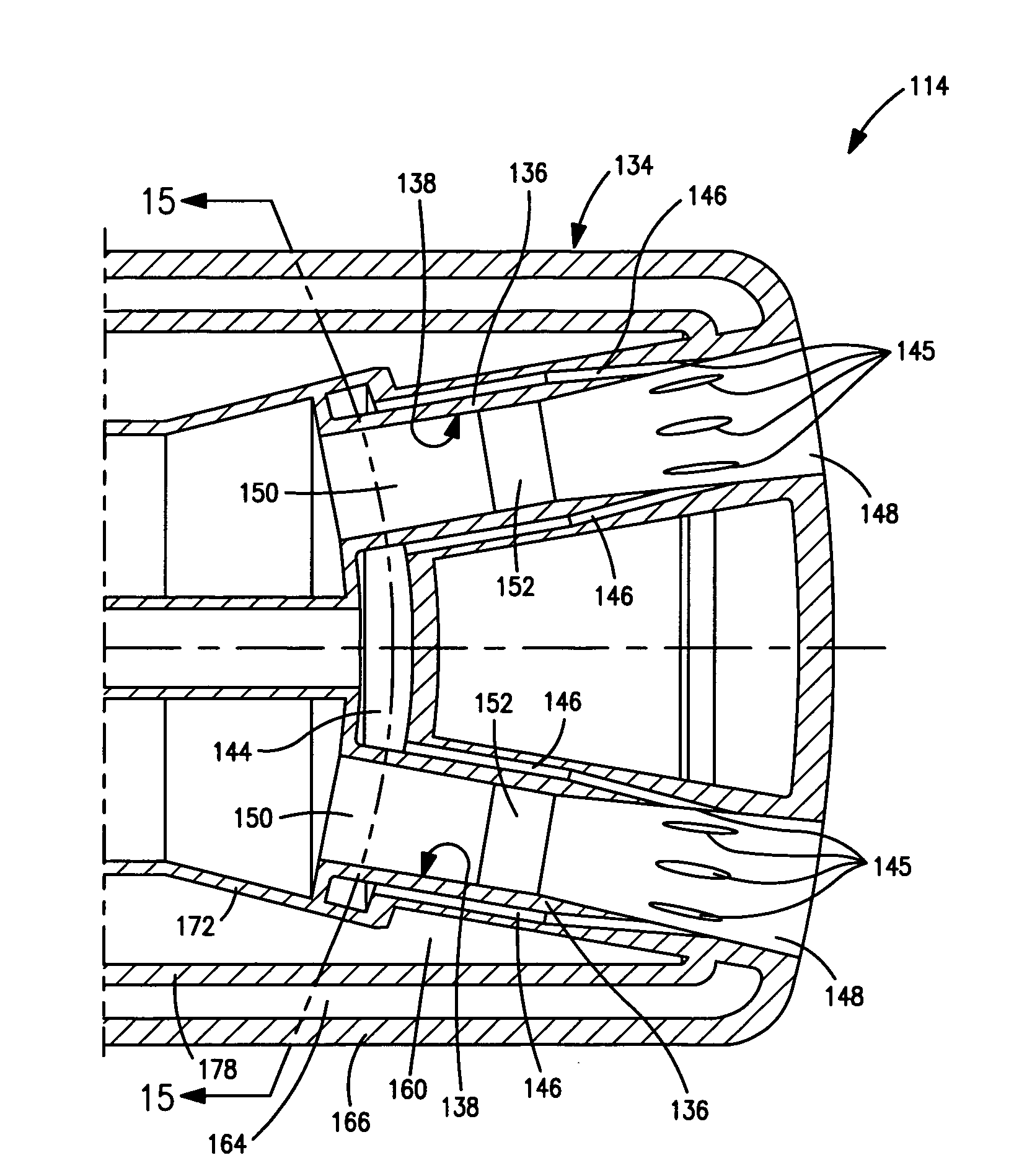
[0045]With reference to FIGS. 1 and 2, the operation of a prior art nozzle 1 that is used to inject a supersonic jet of oxygen into a metallurgical furnace is compared with the operation of a nozzle 2 in accordance with the present invention.

[0046]Nozzle 1 has a passageway 10 of converging-diverging configuration that includes a converging inlet section 12, a central throat section 14 and a diverging outlet section 16 that terminates at a nozzle face 18. When an oxygen stream is injected from a supply passageway 19 into converging inlet section 12 of passageway 10, it undergoes an initial expansion. If the pressure of the oxygen is above what is referred to in the art as “critical pressure” or a “Mach 1 expansion pressure” of the oxygen stream being introduced into nozzle 10, a choked flow condition is achieved in central throat section 14 in which the oxygen has achieved a sonic velocity. The term “sonic velocity” as used herein and in the claims means a velocity that has a magnitu...


PUM

PropertyMeasurementUnit
Angleaaaaaaaaaa
Angleaaaaaaaaaa
Pressureaaaaaaaaaa

Abstract

A method of injecting oxygen into a melt located within a metallurgical furnace having a heated furnace atmosphere in which oxygen and fuel is injected into 1 or more nozzles having passageways of converging-diverging configuration under choked flow conditions to produce supersonic jet or jets discharged from the passageways. Fuel is injected into internal circumferential locations of the passageways so as to impart a structure to the jets being discharged that have an outer circumferential region containing a mixture of fuel and oxygen and a central region containing essentially oxygen. Such a structured jet upon discharge interacts with the furnace atmosphere to create an outer shear-mixing zone in which the outer circumferential layer mixes with the heated furnace atmosphere and auto-ignites to produce a flame envelope surrounding a supersonic jet of oxygen. The jet of oxygen and flame envelope can be directed against a melt contained within the metallurgical furnace for injection of oxygen into the melt.

Description

FIELD OF THE INVENTION [0001]The present invention relates to a method of injecting a supersonic jet of oxygen into a melt located within a metallurgical furnace in which a jet of oxygen is discharged from a convergent-divergent passageway of a nozzle at a supersonic velocity as part of a structured jet having an outer circumferential region composed of a mixture of fuel and oxygen that auto-ignites and combusts in the furnace atmosphere and not within the nozzle to form a flame envelope to inhibit velocity decay and concentration decay of the jet of oxygen.BACKGROUND OF THE INVENTION [0002]Oxygen is typically injected into molten metal baths for such purposes as the refining of steel. For example, steel is refined in electric arc furnaces (EAF) and basic oxygen furnaces (BOF) by injecting oxygen into a melt that contains iron and scrap. The injection of oxygen reacts with carbon, silicon, manganese, iron and impurities that include phosphorus to adjust the carbon content of the mel...

Claims


Application Information

Patent Timeline
IPC IPC(8): C21C5/30
CPCC21C5/4606C21C5/5217F23D14/22Y02E20/344F23D14/48F27D1/16F23D14/32Y02P10/20C21C5/46C21C5/52
Inventor MAHONEY, WILLIAM JOHNRILEY, MICHAEL FRANCISDENEYS, ADRIAN CHRISTIANVARDIAN, GARY THOMASMANLEY, STEPHEN A.
Owner PRAXAIR TECH INC
Features
  • Generate Ideas
  • Intellectual Property
  • Life Sciences
  • Materials
  • Tech Scout
  • Unparalleled Data Quality
  • Higher Quality Content
  • 60% Fewer Hallucinations
Learn More