

Electro-optical device and electronic apparatus
a technology of optical sensors and electronic devices, applied in the direction of static indicating devices, instruments, etc., can solve the problems of deteriorating the visual quality of the display of the liquid crystal device, and the inability to stop the diffusion of external light, so as to achieve high light protection effect, prevent erroneous optical sensor operations, and high light detection accuracy
- Summary
- Abstract
- Description
- Claims
- Application Information
AI Technical Summary
Benefits of technology
Problems solved by technology
Method used
Image

Examples
first embodiment
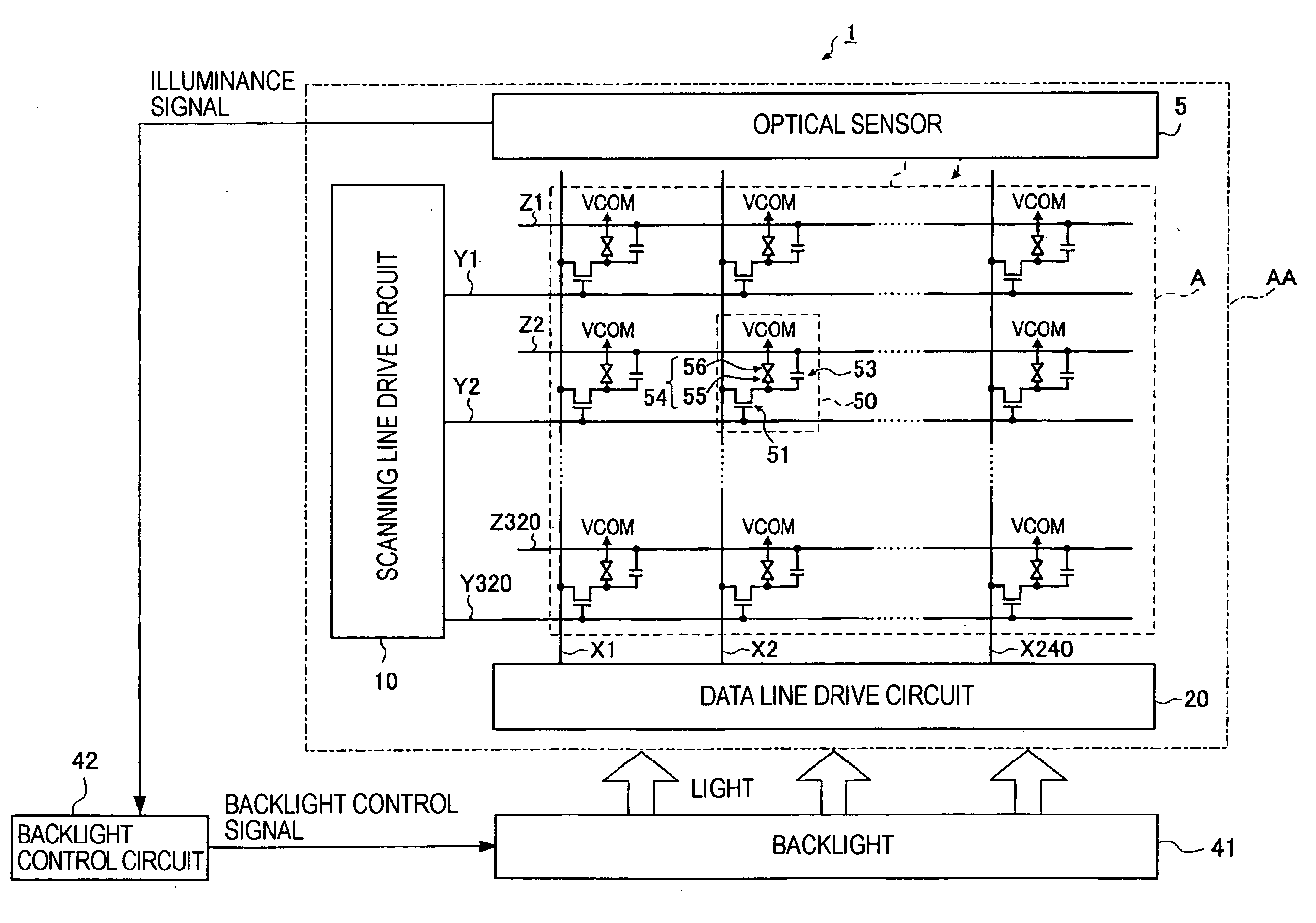
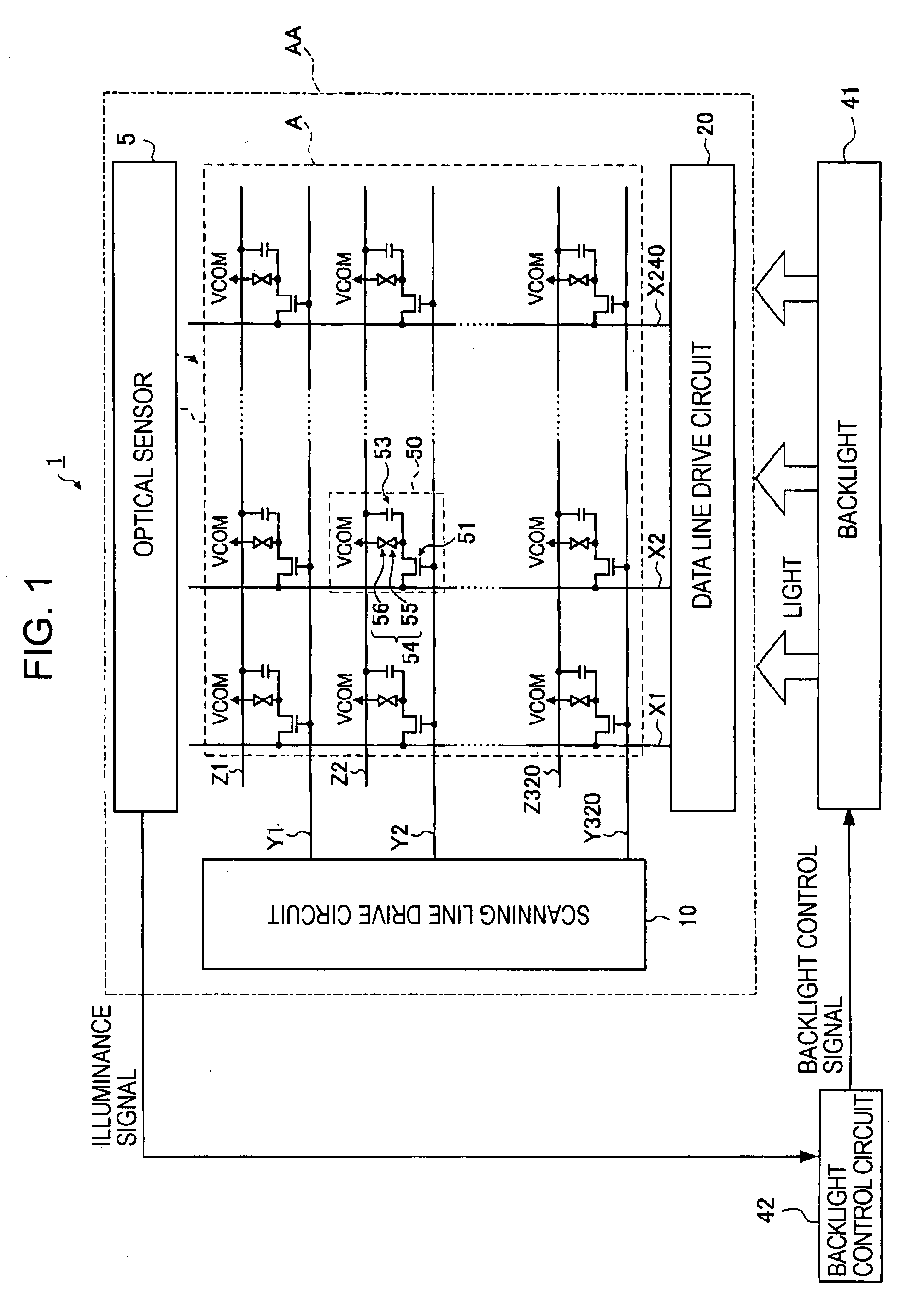
[0035]FIG. 1 is a block diagram illustrating an electro-optical device 1 according to a first embodiment of the invention.
[0036]The electro-optical device 1 includes a liquid crystal panel AA, which serves as an electro-optical panel, a backlight 41, which serves as an illumination unit disposed opposite the liquid crystal panel AA to emit light, and a backlight control circuit 42 that controls the backlight 41. The electro-optical device 1 performs transmissive-mode display by utilizing light emitted from the backlight 41.
[0037]The liquid crystal panel AA includes a display area A having a plurality of pixels 50, an optical sensor 5 that detects the illuminance of external light, and a scanning line drive circuit 10 and a data line drive circuit 20 disposed around the display area A to drive the pixels 50.
[0038]The optical sensor 5 detects the illuminance of external light and outputs an illuminance signal indicating the illuminance of the external light.
[0039]The backlight 41 is d...
second embodiment
[0087]FIG. 6 is a circuit diagram illustrating an optical sensor 5A according to a second embodiment of the invention.
[0088]The optical sensor 5A includes a first PIN diode 81A that receives external light, a second PIN diode 82A that is shielded from external light, and an illuminance detection circuit 90A.
[0089]The anode of the first PIN diode 81A and the anode of the second PIN diode 82A are connected to low potential power supply sources VLL. The cathode of the first PIN diode 81A and the cathode of the second PIN diode 82A are connected to a terminal P and a terminal Q, respectively.
[0090]The current output from the first PIN diode 81A flows in the terminal P, while the current output from the second PIN diode 82A flows in the terminal Q.
[0091]The illuminance detection circuit 90A includes a first detection circuit 91A, a second detection circuit 91B, an exclusive logical OR circuit 95, which serves as a photodetector, a counter 92A, and a LUT 93A. The illuminance detection cir...
applied examples
[0130]Electronic apparatuses using the electro-optical device 1 according to the first or second embodiment are described below.
[0131]FIG. 8 is a perspective view illustrating the configuration of a cellular telephone 3000 to which the electro-optical device 1 is applied. The cellular telephone 3000 includes a plurality of operation buttons 3001, a plurality of scroll buttons 3002, and the electro-optical device 1. Operating the scroll buttons 302 scrolls the screen displayed on the electro-optical device 1.
[0132]Electronic apparatuses to which the electro-optical device 1 is applied include, not only the cellular telephone 3000 shown in FIG. 8, but also personal computers, information portable terminals, digital still cameras, liquid crystal televisions, viewfinder-type or monitor direct-view-type video cassette recorders, car navigation systems, pagers, digital diaries, word-processors, workstations, videophones, point-of-sales (POS) terminals, touch panels, etc. As the display un...
PUM
 Abstract
Description
Claims
Application Information