Component of variable thickness having residual compressive stresses therein, and method therefor

a variable thickness, compressive stress technology, applied in the direction of manufacturing tools, machines/engines, forging/pressing/hammering apparatus, etc., can solve the problems of reducing the life of parts, repair or replacement, and composite components that are susceptible to fatigue and damage cracking, etc., to reduce crack propagation in components, and reduce the propagation of cracks in components

Inactive Publication Date: 2008-01-03
GENERAL ELECTRIC CO
View PDF4 Cites 8 Cited by
  • Summary
  • Abstract
  • Description
  • Claims
  • Application Information

AI Technical Summary

Benefits of technology

[0013]According to another aspect of the invention, a method of reducing crack propagation in components includes: providing a component having an exterior surface; and using a burnishing element to apply a varying pressure to the exterior surface within a selected area, within which the component has a varying thickness, so as to create a region of residual compressive stress surrounded by an interior boundary; wherein the distance from the interior boundary to the exterior surface at any given location within the selected area is independent of the thickness of the component at that location.
[0014]According to another aspect of the invention, a method of reducing crack propagation in components includes providing a component having opposed, spaced-apart first and second exterior surfaces; and using first and second burnishing elements to apply a varying pressure to the exterior surfaces within respective first and second selected areas, within which the component has a varying thickness, so as to create first and second regions of residual compressive stress surrounded by first and second interior boundaries. The distance from each of interior boundaries to the respective exterior surface at any given location within the respective selected area is independent of the thickness of the component at that location.
[0015]According to another aspect of the invention, a method of reducing crack propagation in components, includes: providing a component having opposed, spaced-apart first and second exterior surfaces; and using a first burnishing element to apply a pressure to the first exterior surface within a first selected area, within which the component has a varying thickness, while moving the first burnishing element along a first preselected path including segments separated by a step-over distance, so as to create a first region of residual compressive stress surrounded by a first interior boundary; wherein the step-over distance is selected to control an amount of overlap between adjacent segments, consequently changing the distance from the first interior boundary to the first exterior surface, such that the distance from the interior boundary to the first exterior surface at any given location within the first selected area is independent of the thickness of the component at that location.

Problems solved by technology

Various metallic, ceramic, and composite components, such as gas turbine engine fan and compressor blades, are susceptible to cracking from fatigue and damage (e.g. from foreign object impacts).
This damage reduces the life of the part, requiring repair or replacement.
However, this would result in excessive compressive stress levels near the trailing edge 32, because of overlap of the regions 50 and 52.
It could also damage the airfoil 22 and result in undesired deformation.

Method used


Image

  • Component of variable thickness having residual compressive stresses therein, and method therefor
  • Component of variable thickness having residual compressive stresses therein, and method therefor
  • Component of variable thickness having residual compressive stresses therein, and method therefor

Examples


Embodiment Construction

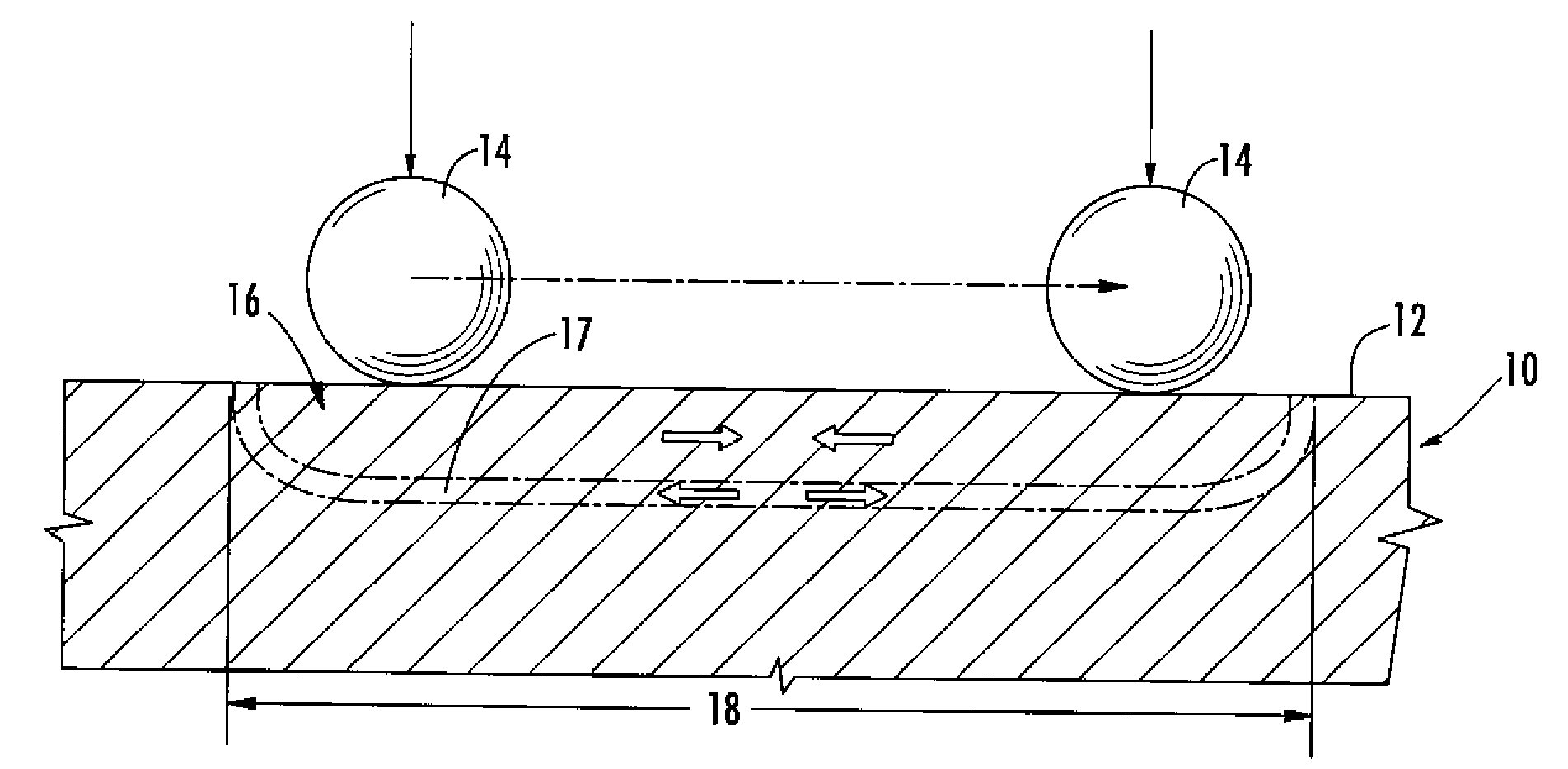
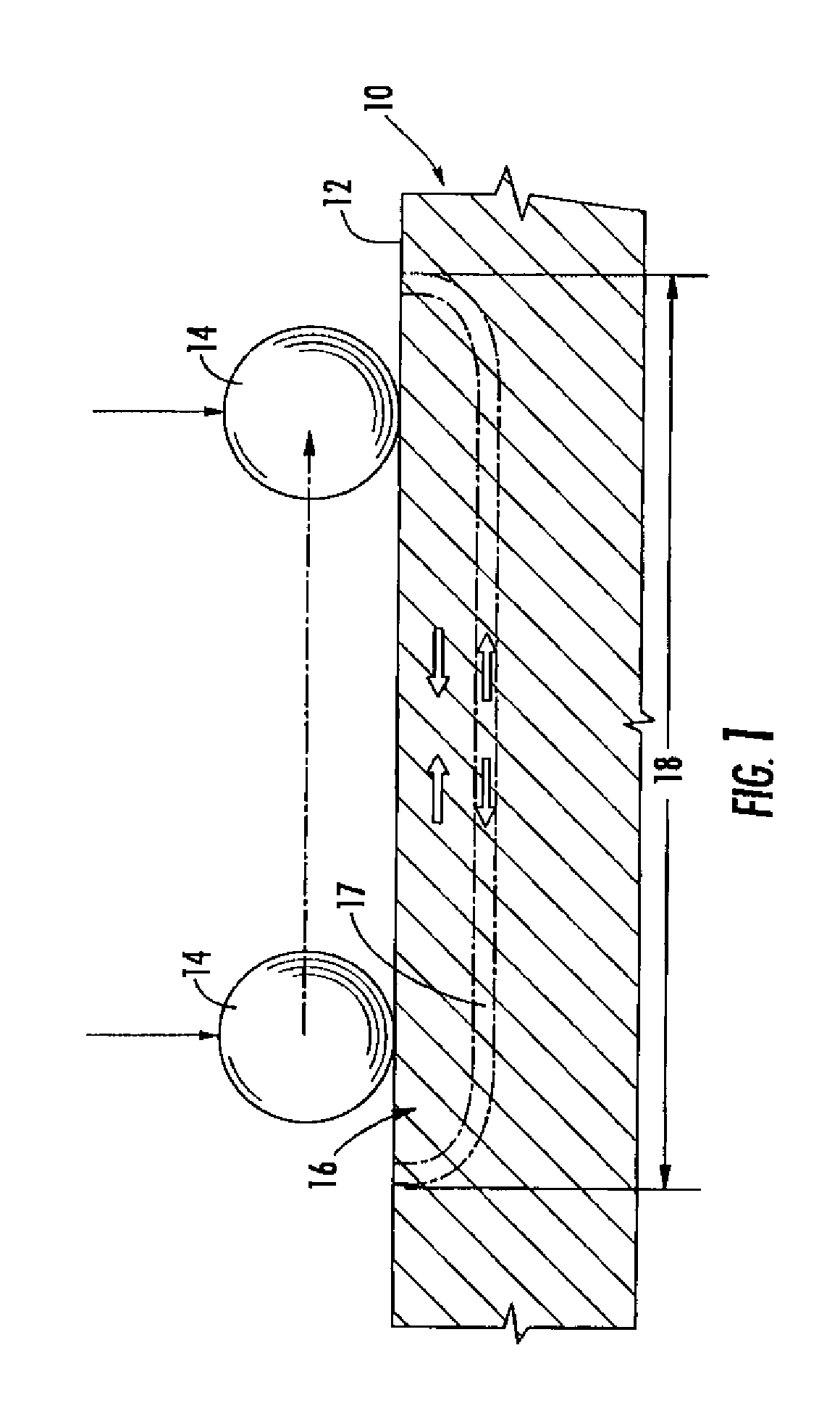
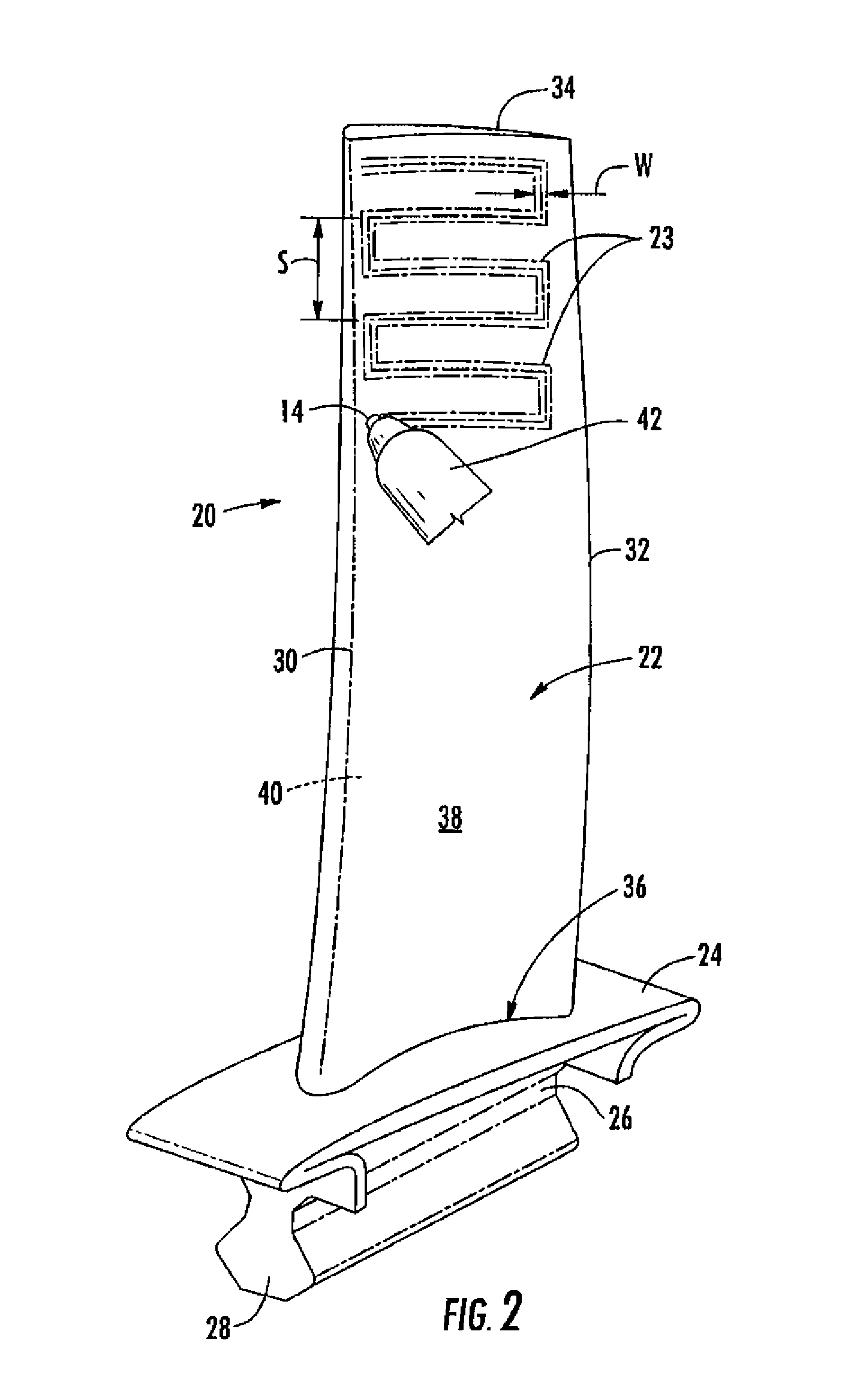
[0024]FIGS. 4A and 4B illustrate an exemplary burnishing treatment in accordance with an aspect of the invention being applied to the trailing edge region of an airfoil 122, which before treatment is identical to the airfoil 22 described above. FIG. 4A shows the treatment being applied to the pressure side 138 within a selected area by a burnishing element 114, while the airfoil 122 is supported by a block 144. The treatment described herein may be applied to any portion of the airfoil 122. In this case, the applied pressure in a direction normal to the surface, indicated at F, is selected to generate a region 146 of residual compressive stress which has a depth D (this could also be described as penetration) measured from the surface of the suction side 138, and expressed as expressed as a fraction of the total thickness of the airfoil 122 at the point of measurement. To achieve a more uniform depth D, the burnishing parameters are changed as the burnishing element 114 moves to are...


PUM

PropertyMeasurementUnit
residual compressive stressaaaaaaaaaa
thicknessaaaaaaaaaa
compressive stressaaaaaaaaaa

Abstract

A method of reducing crack propagation includes: providing a metallic component having an exterior surface, and using a burnishing element to apply a varying to the exterior surface within a selected area, within which the component has a varying thickness, so as to create a region of residual compressive stress of surrounded by an interior boundary. The distance from the interior boundary to the exterior surface at any location within the selected area is independent of the thickness of the component at that location, and may be controlled by changing the pressure and/or an amount of overlap between burnished segments.

Description

BACKGROUND OF THE INVENTION[0001]This invention relates generally to fatigue-resistant and damage-tolerant components and methods of producing such components.[0002]Various metallic, ceramic, and composite components, such as gas turbine engine fan and compressor blades, are susceptible to cracking from fatigue and damage (e.g. from foreign object impacts). This damage reduces the life of the part, requiring repair or replacement.[0003]It is known to protect components from crack propagation by inducing residual compressive stresses therein. Methods of imparting these stresses include shot peening, laser shock peening (LSP), pinch peening, and low plasticity burnishing (LPB). These methods are typically employed by applying a “patch” of residual compressive stresses over an area to be protected from crack propagation, for example a leading edge of a gas turbine engine compressor blade.[0004]During a burnishing operation, the depth of the compressive residual stress layer can be cont...

Claims


Application Information

Patent Timeline
Patent Type & Authority Applications(United States)
IPC IPC(8): B64C27/46
CPCB23P9/02B24B39/00C21D7/08C21D2221/00C21D2221/10Y10T29/4932F05D2260/94F05D2230/26F05D2230/20F05D2230/90F01D5/286
Inventor LUNA, ALBERTOMILLER, JOSHUA LEIGH
Owner GENERAL ELECTRIC CO
Why Eureka
Try Eureka