
Particle Laminated Substate and Method for Manufacturing the Same

a technology of particle laminated sub-states and manufacturing methods, applied in the direction of thin material processing, instruments, coatings, etc., can solve the problems of unsuitable process as a practical method for forming films from particles, and the orientation of particles, particularly those of nanoparticles, cannot be controlled in the particle accumulation layer

Inactive Publication Date: 2008-01-03
FUJIFILM CORP
View PDF1 Cites 22 Cited by
  • Summary
  • Abstract
  • Description
  • Claims
  • Application Information

AI Technical Summary

Benefits of technology

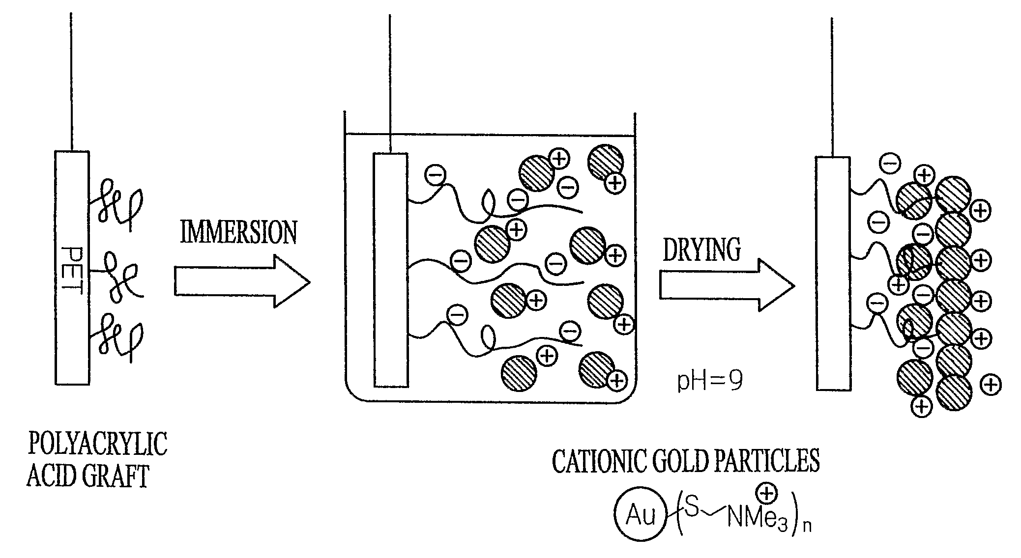
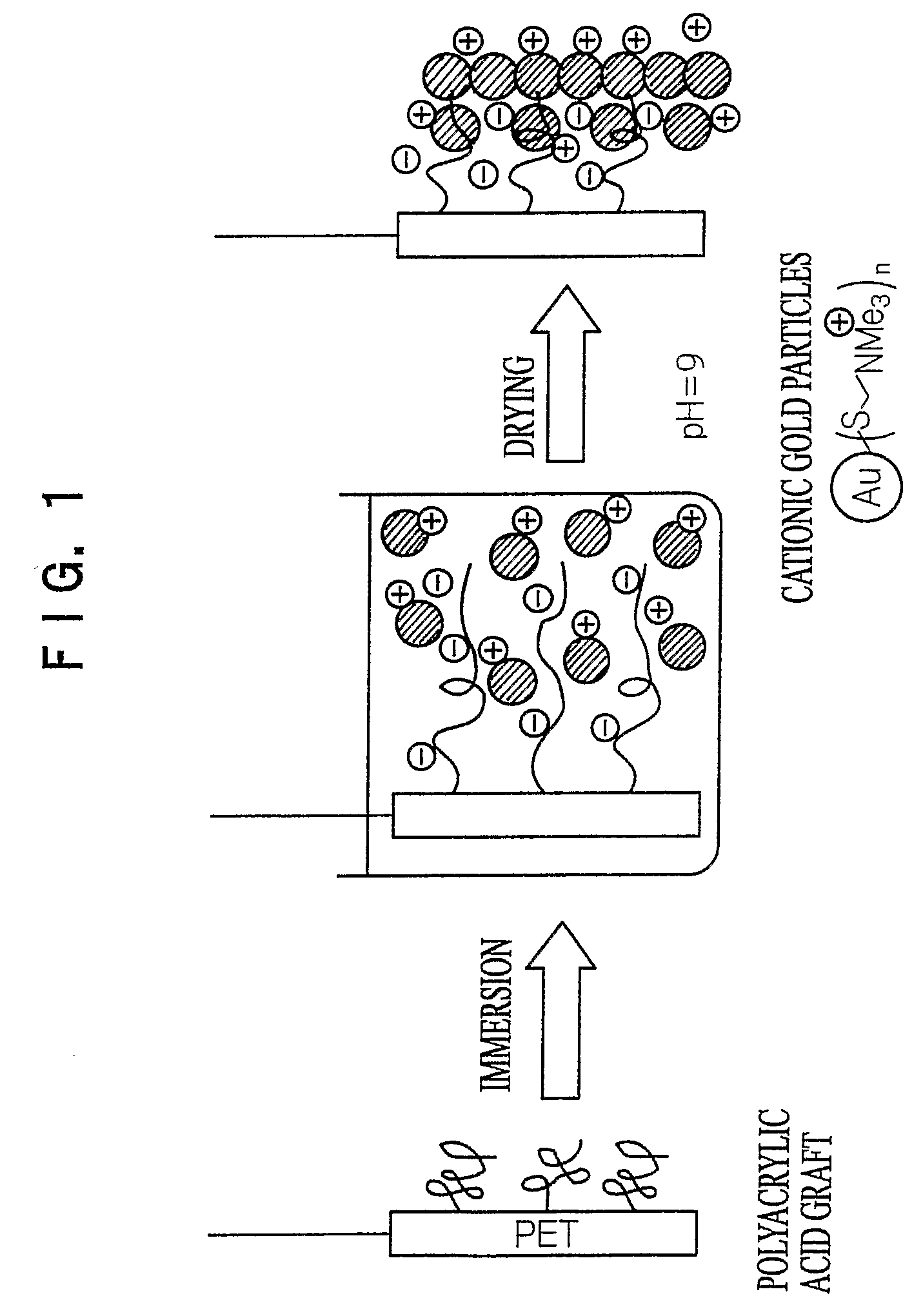
[0005] The invention has been made in view of the situation as described above. The invention provides a particle laminated substrate having a high-quality particle accumulation layer formed on a substrate wherein functional particles are distributed unevenly so as to have a concentration gradient in the particle accumulation layer with a high density in the vicinity of a surface and a low density in the deep portion of the particle accumulation layer. Furthermore, the invention provides a novel method for manufacturing a particle laminated substrate by which the particle laminated substrate wherein functional particles distributed in a high density in the vicinity of a surface of a particle accumulation layer can be easily formed by simple steps through controlling a method for accumulating particles.

Problems solved by technology

However, the method involves complicated steps such as allowing the adsorption of particles, then, covering them with a resin, and further allowing adsorption of the particles but this procedure is unsuitable as a practical method for forming film from particles.
Accordingly, an orientation of particles, particularly that of nanoparticles, cannot be controlled in the particle accumulation layer.

Method used


Image

  • Particle Laminated Substate and Method for Manufacturing the Same
  • Particle Laminated Substate and Method for Manufacturing the Same
  • Particle Laminated Substate and Method for Manufacturing the Same

Examples


example 1

Preparation of Substrate Having Graft Polymer on Surface Thereof

(Synthesis of Silane Terminal Initiator SiP: Phenyl-[1-(11-trichlorosilanyl-undesiloxy)-cyclohexyl]-methanone)

[0090] Nitrogen was flowed through a calcium chloride tube fitted to a 1000 ml three-necked flask. 28.6 g (0.14 mol) of 1-hydroxycyclohexylphenylketone were dissolved in a mixed solvent of 60 g of dimethylacetamide (DMAc) dehydrated with a molecular sieve in the flask and 60 g of tetrahydrofuran (THF) dehydrated as described above, and 8.4 g (0.21 mol) of sodium hydride (NaH) (60 to 72% in oil) were gradually added to the resulting solution in an ice bath. To the solution, 51.6 g (0.21 mol) of 11-bromo-1-undecene (95%) was dropped to react with them at room temperature. As a result of a reaction trace with TLC, the reaction was completed for one hour.

[0091] The reaction solution was introduced in ice water, extracted with ethyl acetate, and concentrated. Then, 74.2 g of the resulting mixture were picked up, ...


PUM

PropertyMeasurementUnit
thicknessaaaaaaaaaa
particle diameteraaaaaaaaaa
thicknessaaaaaaaaaa

Abstract

A particle laminated substrate and a method for manufacturing the particle laminated substrate are disclosed. The particle laminated substrate has a particle accumulation layer formed by accumulating and allowing particles to adhere onto a substrate having a surface where a graft polymer chain is present in which either terminal of the polymer is bonded to the surface of the substrate, by means of an electrostatic accumulating phenomenon, such that a particle density in the vicinity of the surface of the particle accumulation layer is higher than a particle density in the vicinity of the substrate.

Description

TECHNICAL FIELD [0001] The invention relates to a particle laminated substrate having a particle accumulation layer in which particles, particularly nanoscale diameter particles, accumulate and adhere such that the particles are distributed unevenly so as to have a concentration gradient in the particle accumulation layer with a high density in the vicinity of a surface and a low density in the deep portion of the particle accumulation layer, and a method for manufacturing the same. Specifically, the invention relates to a substrate having a multilayer particle accumulation layer which is novel and useful as a functional material in a wide range of industrial fields such as electroconductive films, optical films, biosensors, gas barrier films and the like, and a method for manufacturing the same. BACKGROUND ART [0002] Various approaches for developing useful functional materials wherein a particle layer is formed on a substrate and the functions of the particle are effectively used ...

Claims


Application Information

Patent Timeline
Patent Type & Authority Applications(United States)
IPC IPC(8): B05D7/00B32B5/00
CPCB05D1/007B05D1/18Y10T428/254B05D7/02B05D1/185G02B1/10B32B5/16
Inventor KAWAMURA, KOICHI
Owner FUJIFILM CORP
Learn More