Fluorometric apparatus, fluorometric method, container for fluorometry, and method of manufacturing container for fluorometry

a technology of fluorometric and container, which is applied in the direction of optical radiation measurement, instruments, spectrophotometry/monochromator, etc., can solve the problem that the examination results cannot be obtained in a short time in a consulting room, and achieves the effect of high spatial utilization rate, simple and easy to opera

Inactive Publication Date: 2008-01-03
SANKO JUNYAKU CO LTD +1
View PDF5 Cites 15 Cited by
  • Summary
  • Abstract
  • Description
  • Claims
  • Application Information

AI Technical Summary

Benefits of technology

[0011] An object of the present invention is to provide a fluometry and a fluometric apparatus which are simple and easy in ope

Problems solved by technology

However, in the prior art method, these operations are usually complicated works that are to be performed by a medical

Method used


Image

  • Fluorometric apparatus, fluorometric method, container for fluorometry, and method of manufacturing container for fluorometry
  • Fluorometric apparatus, fluorometric method, container for fluorometry, and method of manufacturing container for fluorometry
  • Fluorometric apparatus, fluorometric method, container for fluorometry, and method of manufacturing container for fluorometry

Examples


first embodiment

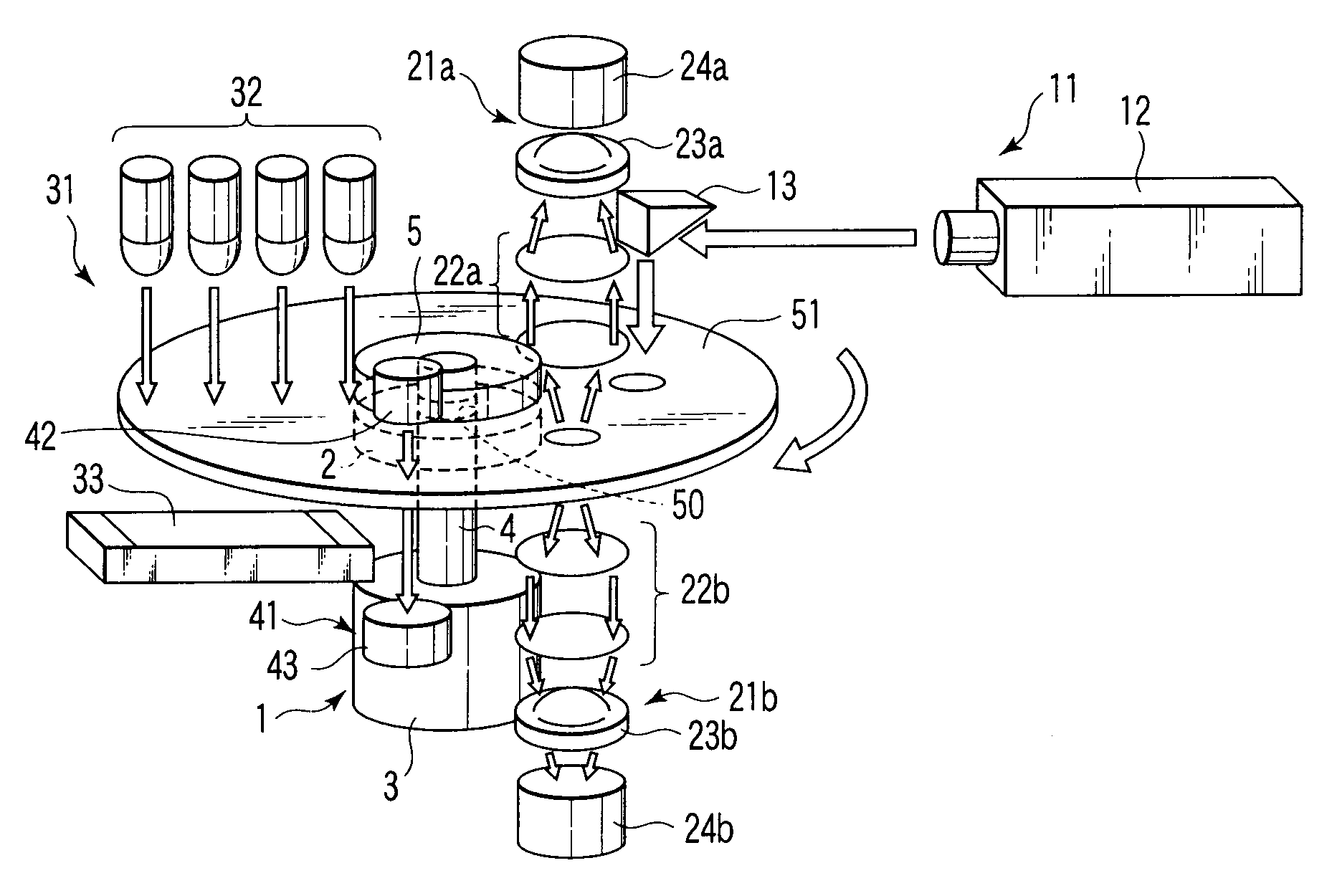
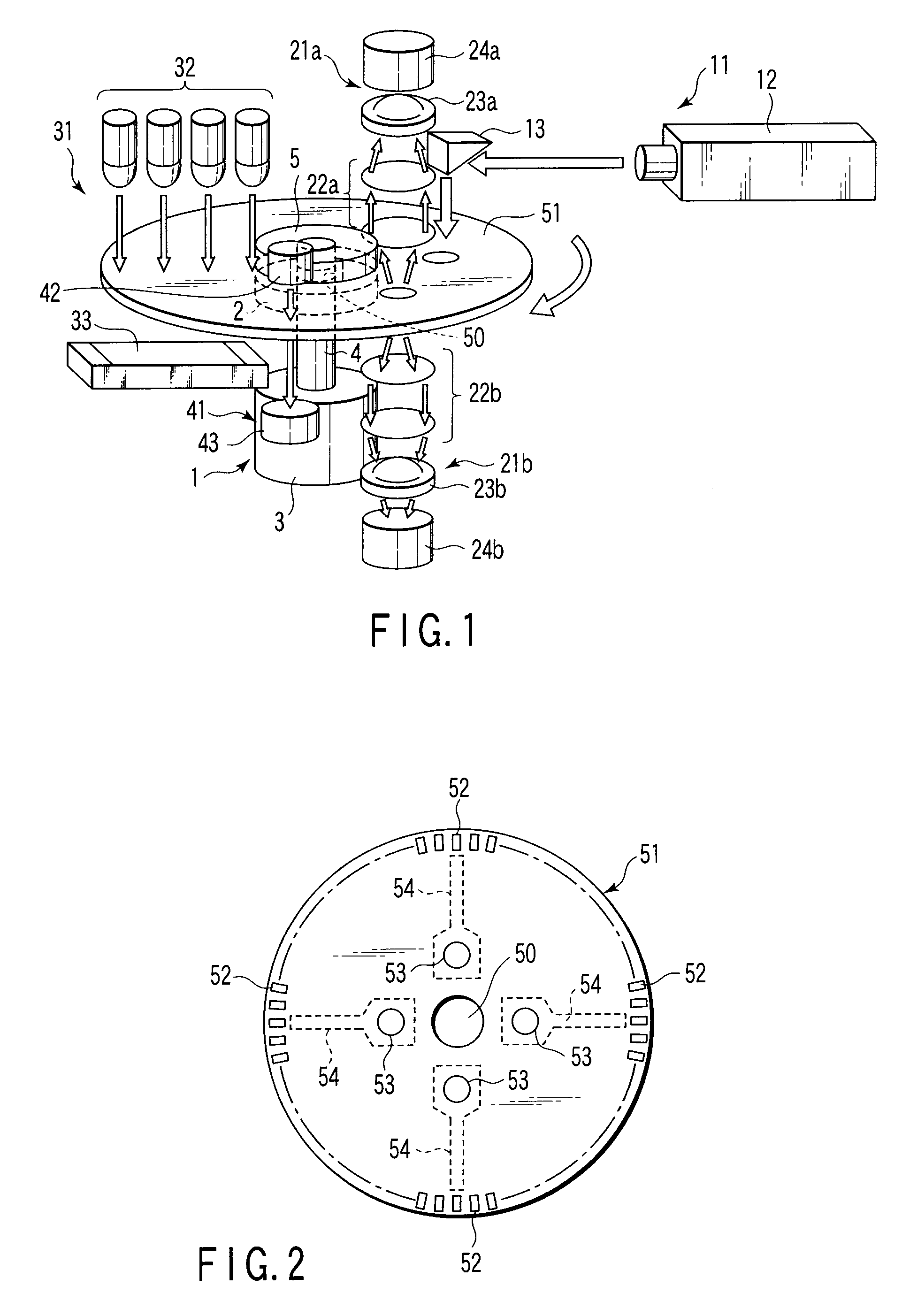
[0085]FIG. 1 is an oblique view showing a fluorometric apparatus according to a first embodiment.

[0086] The fluorometric apparatus according to the first embodiment comprises a turntable 1 which detachably supports a container 51 having a hole 50 at the center thereof and containing therein a specimen to be examined containing a protein labeled with a fluorescent dye that emits fluorescence of a predetermined wavelength by being excited by predetermined excitation light, and which rotates the container 51 so as to subject the container 51 to centrifugal separation, an excitation light irradiator 11 which is arranged beside the turntable 1, and emits excitation light toward the container 51, a pair of fluorescence detecting units 21a and 21b which are arranged around the turntable 1 at a desired angle with respect to the excitation light irradiator 11, receive the fluorescence emitted from the container 51, and output electric signals corresponding to received amounts of fluorescenc...

second embodiment

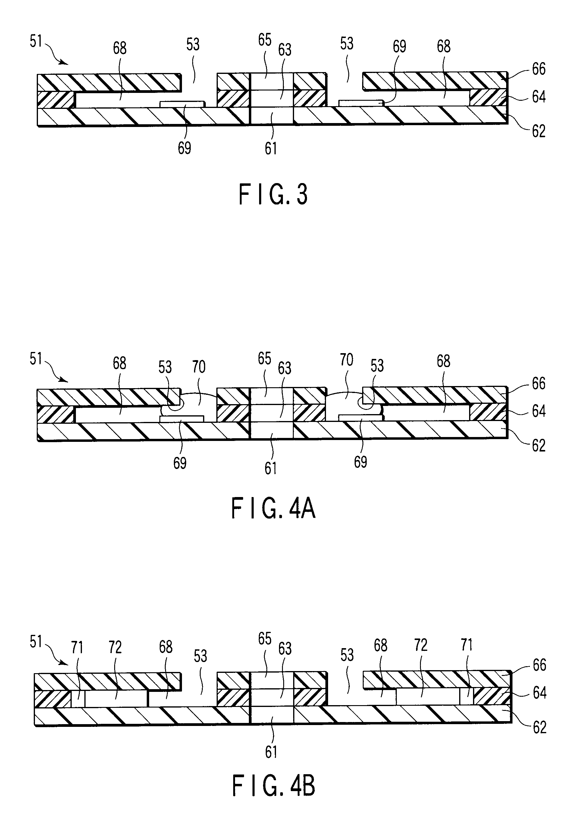
[0128]FIGS. 6A to 6D are views showing a manufacturing process of a container according to a second embodiment. Incidentally, the left side of the drawing is a cross-sectional view of a right half part of the container, and the right side thereof is a plan view of the vicinity of the cross section viewed from the top surface (the principal surface side on which specimen pouring openings are formed).

[0129] As shown in FIG. 6A, a transparent flat plate having a hole 61 formed in the center, i.e., a first disk 62 is manufactured by injection molding using a thermoplastic resin material containing an acrylic resin as a principal material.

[0130] Then, as shown in FIG. 6B, a specimen reception spacer 64 with a hole 63 in the center, having a disk-like shape, and having grooves 68 formed therein is stuck to one principal surface of the first disk 62 such that holes 61 and 63 coincide with each other. A plurality of rectangular marks 52 used for position sensing are formed on the entire o...

third embodiment

[0138]FIGS. 8A to 8E are views showing a manufacturing process of a container according to a third embodiment. Incidentally, the left side of the drawing is a cross-sectional view of a right half part of the container, and the right side thereof is a plan view of the vicinity of the cross section viewed from the top surface (the principal surface side on which the specimen pouring openings are formed).

[0139] As shown in FIG. 8A, a transparent flat plate having a hole 61 formed in the center, i.e., a first disk 62 is manufactured by injection molding using a thermoplastic resin material containing an acrylic resin as a principal material.

[0140] Then, as shown in FIG. 8B, a specimen reception spacer 64 with a hole 63 in the center, having a disk-like shape, and having grooves 68 formed therein is stuck to one principal surface of the first disk 62 such that holes 61 and 63 coincide with each other. A plurality of rectangular marks 52 used for position sensing are formed on the entir...


PUM


Abstract

A fluorometric apparatus capable of configuring to have a small size and operability requiring a simple and easy operation of centrifuging a specimen in a container a rotation center of which is detachably supported by a rotation axis (not shown), exciting the specimen by means of an N2 laser apparatus and an excitation light irradiator for guiding the laser light emitted from the N2 laser apparatus, and receiving fluorescence having two types of wavelengths emitted from antibodies labeled with fluorescent dyes in the specimen in a region separate from the region in which the excitation light is radiated by a predetermined angle by using a photomultiplier tube, obtaining a ratio of light intensity for each wavelength, comparing the obtained ratio with a standard value, and estimating a target protein concentration.

Description

CROSS-REFERENCE TO RELATED APPLICATIONS [0001] This is a Continuation Application of PCT application No. PCT / JP2006 / 306929, filed Mar. 31, 2006, which was published under PCT Article 21(2) in Japanese. [0002] This application is based upon and claims the benefit of priority from prior Japanese Patent Applications No. 2005-105169, filed Mar. 31, 2005; No. 2005-138914, filed May 11, 2005; and No. 2005-160044, filed May 31, 2005, the entire contents of all of which are incorporated herein by reference.BACKGROUND OF THE INVENTION [0003] 1. Field of the Invention [0004] The present invention relates to a fluorometric apparatus, fluorometric method, container for fluorometry, and method of manufacturing a container for fluorometry. More specifically, the present invention relates to a fluorometric apparatus for measuring the intensity of fluorescence radiated from a fluorescent dye in a solution used in clinical laboratory examination mainly using a fluorescent dye called FRET (fluorescen...

Claims


Application Information

Patent Timeline
IPC IPC(8): C12M1/34G01J3/42
CPCG01N21/07G01N21/645G01N21/6428
Inventor UCHIYAMA, KENICHIKASAI, SHINGOUEMATSU, IKUOTAKASE, TOMOHIROOOMIYA, KAYOKOTONO, ICHIROSEKINO, TETSUOISHIOKA, SEIICHIROUKAWAMURA, TAKASHI
Owner SANKO JUNYAKU CO LTD
Why Eureka
Try Eureka