Power transmission belt and a process for its manufacture

Active Publication Date: 2008-01-03
THE GATES CORP
View PDF9 Cites 29 Cited by
  • Summary
  • Abstract
  • Description
  • Claims
  • Application Information

AI Technical Summary

Benefits of technology

[0013]In a further embodiment of the present invention, a method for producing a power transmission belt is provided comprising the steps of applying to a fabric element a mixture comprising an internal lubricating agent and a carrier; and allowing at least a significant portion of the carrier to liberate, and at least a portion of the internal lubricating agent to form one or more clusters within at least a portion of the total thickness of the fabric cover element.
[0014]In yet another embodiment of the pre

Problems solved by technology

Under such high load, high temperature and/or high-speed conditions, it is common for the teeth of endless toothed belts to deteriorate; the severe shearing stresses on the teeth often result in crack generation and tooth loss.
This modification alone however has not proved completely satisfactory in some particularly demanding applications.
Upon extended high load or high-speed operation, such fabric covers tend to wear away, resulting in dimensional changes and/or premature belt failure.
Moreover, there is a tendency in such constructions for the underlying belt elastomer to migrate through the weave of the fabric cover during the curing process and/or upon operation, and/or for the fabric cover to wear away with prolonged use, and to thus present some portion of the underlying belt elastomer at the belt's power transmitting surface.
The presence of this relatively high coefficient of friction material at the belt's power transmitting surface results in high noise and frictional heat generation at the belt-sprocket interface upon operation of the belt.
Noise generation is viewed as highly undesirable, and frictional heat generation and heat build-up reduce the life of the belt.
None of these approaches to the problems of abrasion or wear, noise and/or frictional heat generation in endless belt constructions is believed to be completely satisfactory, particularly in very high load applications.
Where the belt surface remains free of belt elastomer by means of a relatively poor abrasion-resistant or low temperature laminate coating on the outer surface of a fabric cover element, high load or high temperature operation generally results in flaking off or melting of the coating, res

Method used


Image

  • Power transmission belt and a process for its manufacture
  • Power transmission belt and a process for its manufacture
  • Power transmission belt and a process for its manufacture

Examples


Embodiment Construction

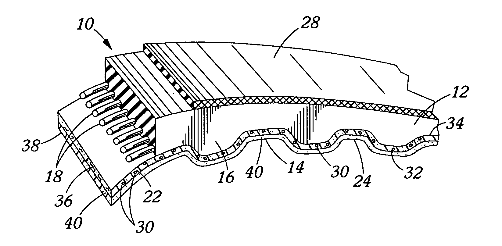
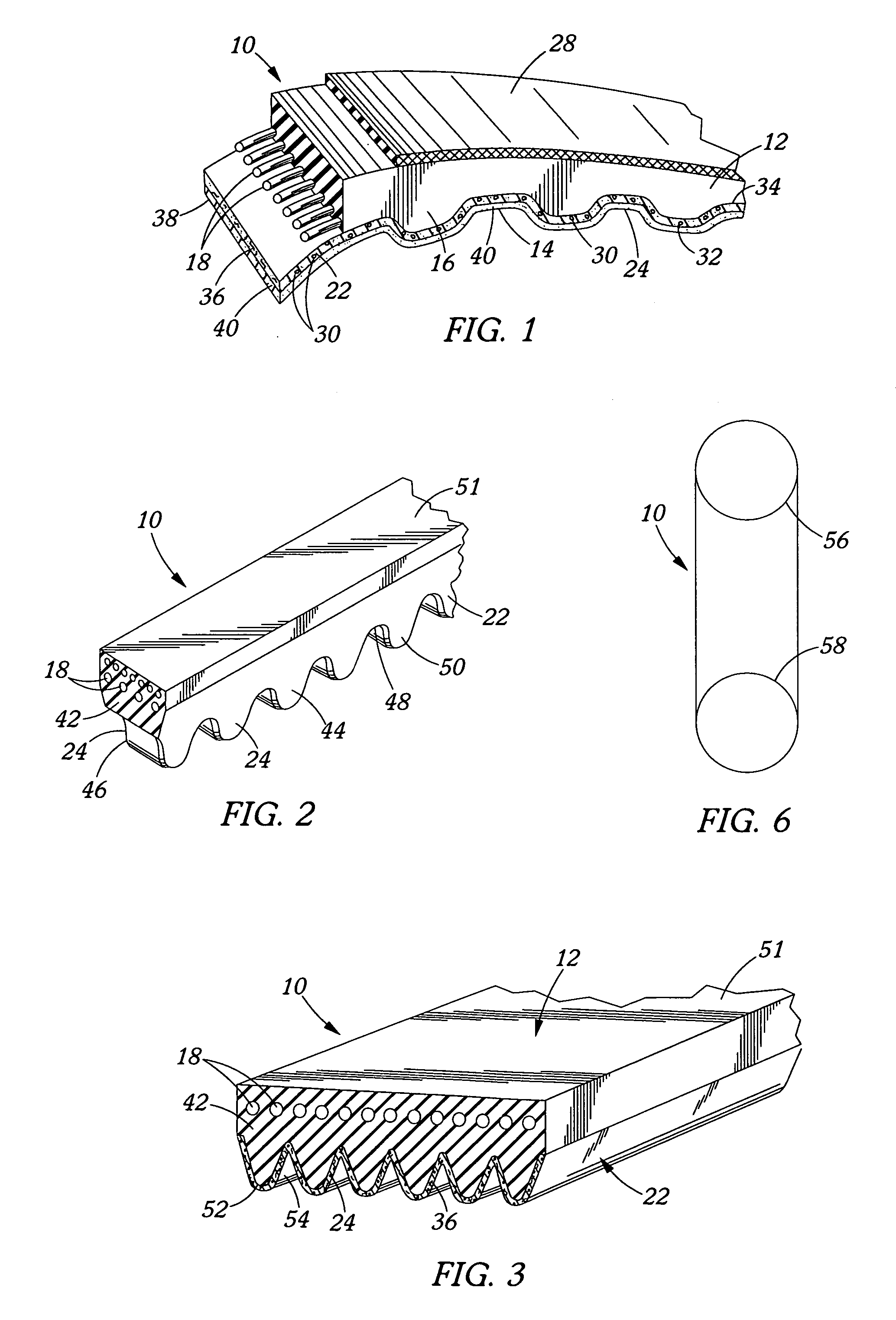
[0022]Referring to FIG. 1, an endless toothed power transmission belt 10 is shown generally. The belt includes a body having an overcord section 12 formed from a generally flexible material and a series of spaced cogs or teeth 16, also comprising a suitable generally flexible material alternating with land portions 14. The generally flexible material or materials utilized in the overcord section 12 and teeth 16 should generally be compatible with one another and may be of the same or of different types of material. Any suitable and / or conventional elastomer, including both castable and non-castable elastomers, may be used as the overcord 12 and / or the teeth 16 (hereafter collectively, “the belt body portions”) in this embodiment of the present invention. Examples of suitable castable elastomers include but are not limited to castable polyurethanes (including polyurethanes, polyurethane / ureas and polyureas), plastisols, organosols, liquid chloroprenes, liquid polysulfides, liquid rub...


PUM


Abstract

An endless power transmission belt having a internal lubricating agent-containing fabric element extending along at least the pulley-engaging, power-transmitting surface of the belt, as well as processes for manufacturing same. More particularly, an endless toothed belt having a wear-resistant fabric cover element that comprises at least one internal lubricating agent in the form of one or more clusters within at least a portion of the total thickness of the fabric element.

Description

BACKGROUND OF THE INVENTION[0001]The present invention relates to an endless belt having a power transmitting surface exhibiting high wear resistance, and more particularly to endless toothed belts having a fabric cover element intimately positioned along at least the outer surface of the tooth and land portions of the belt, and having a lubricating agent present within at least a portion of the fabric cover element, and optionally including a lubricating agent on at least a portion of the outer surface thereof, as well as to a method for producing such belts.[0002]Endless belts, including V-belts, V-ribbed belts, and flat belting, as well as toothed belts such as synchronous- or timing belts and the like, are used in a variety of applications. Examples of power transmission belts, including toothed or synchronous belts, V-belts, and V-ribbed belts are disclosed in U.S. Pat. Nos. 3,138,962; 3,200,180; 4,330,287; and 4,332,576. Examples of methods for producing such belts are disclos...

Claims


Application Information

Patent Timeline
IPC IPC(8): F16G1/28
CPCB29D29/08F16G5/20F16G1/28
Inventor DUKE, JOSEPH RALEIGHYU, TAO
Owner THE GATES CORP
Why Eureka
Try Eureka