Rigid random coils and composition comprising the same

a random coil and coil technology, applied in the field of random coils, can solve the problems of large change in strength of random coils, unfinished research on them, and inability to meet the requirements of the application of random coils, so as to achieve efficient application and mitigate problems

Active Publication Date: 2008-01-03
LG CHEM LTD
View PDF4 Cites 5 Cited by
  • Summary
  • Abstract
  • Description
  • Claims
  • Application Information

AI Technical Summary

Benefits of technology

[0016] As described hereinbefore, the present invention provides rigid random coils and a resin composition comprising the same. In the case where the rigid random coils according to the present invention are mixed with an organic solvent or a polymer and are thus used as an electrically conductive coating agent or plastic, isotropic material can be formed, unlike conventional rod conductive fillers. Further, in the case where the rigid random coils of the present invention serve as a reinforcing agent for plastics, they can be used as additives or fillers in various organic solvents and polymers because they mitigate problems related to the anisotropy of conventional rod reinforcing filler. In this way, the rigid random coils of the present invention are expected to be efficiently applied to related fields.

Problems solved by technology

However, the rigid rod is disadvantageous because it is in a liquid crystal state at a specific concentration and thus undesirably undergoes phase separation, and also the strength thereof changes considerably according to its orientation.
However, research thereon has not yet been conducted.

Method used


Image

  • Rigid random coils and composition comprising the same
  • Rigid random coils and composition comprising the same
  • Rigid random coils and composition comprising the same

Examples


example 1

Preparation of Rigid Random Coils and Thin Film

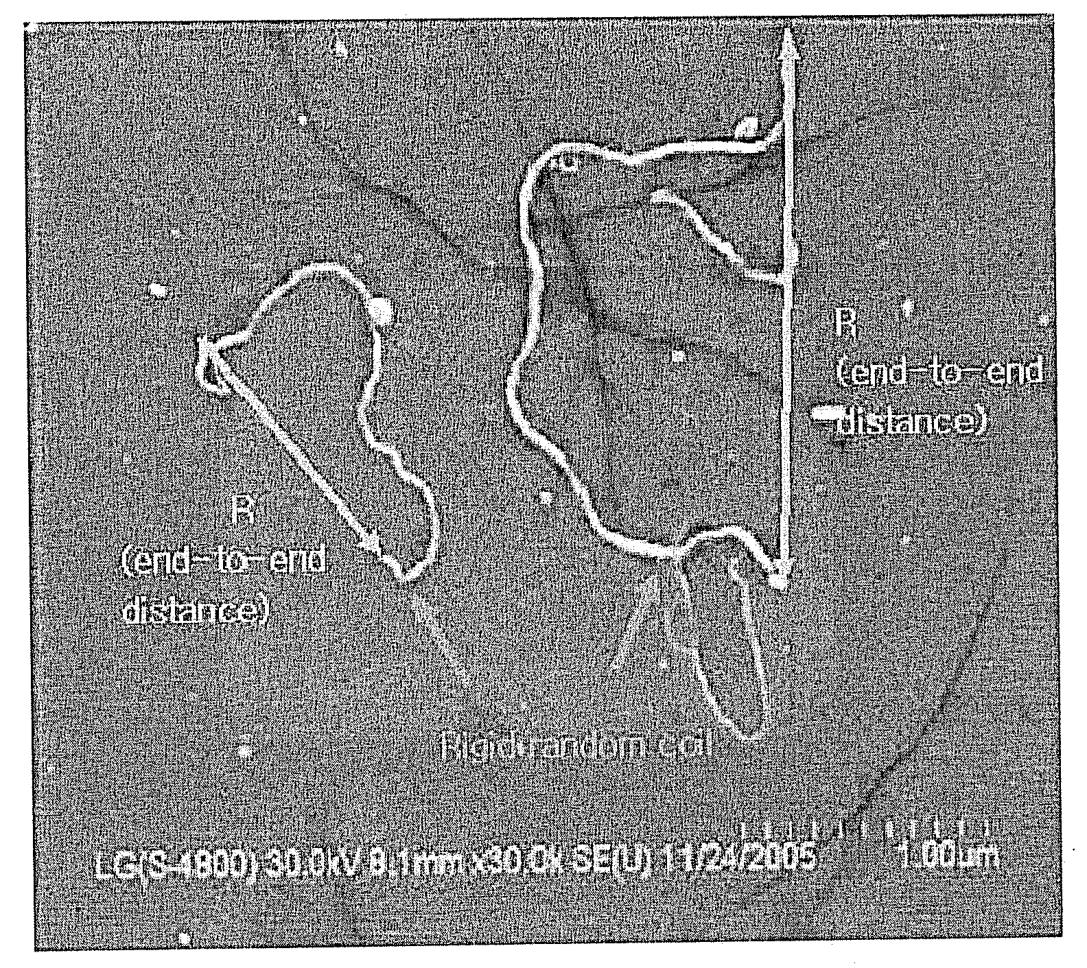
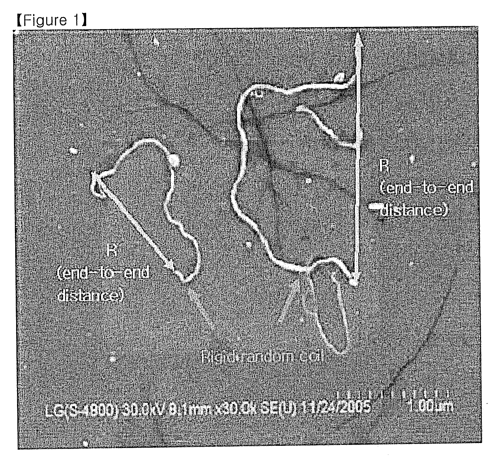
[0056] 5 g of a multi-walled carbon nanotube aggregate (available from JEIO Co., Ltd.), obtained by supporting a metal (Fe) catalyst on ceramic powder (aluminum oxide) and then performing chemical vapor deposition, was added to 100 g of purified water, and then sonication was conducted at 40 W for 180 min. 50 g of 60% strong nitric acid was added thereto, and then sonication was performed at 40 W for 60 min, so that the aggregate was cut and separated and the ceramic powder was dissolved. Subsequently, the product was washed with purified water, added to 100 g of dimethylformamide, and then subjected to sonication at 40 W for 180 min. The sonicated solution was centrifuged, thus obtaining rigid random coils in the uniform solution, the bending ratio and the weight average molecular weight of which were measured to be 0.32 and 3.43×10⁸ g / mole, respectively. The rigid random coils thus prepared were filtered, resulting in a thin film, th...

example 2

[0057] A uniform solution of dimethylformamide and rigid random coils, obtained as in Example 1, was mixed with polycarbonate dissolved in THF so that the rigid random coils were contained in an amount of 0.5 wt %, followed by film casting. The rigid random coils thus prepared were filtered to thus obtain a thin film 1 μm thick, the surface resistance of which was measured to be 104˜8 Ohm / sq.

example 3

Carbon Fiber Rigid Random Coils

[0058] The present example was conducted in the same manner as in Example 1, with the exception that carbon fiber, rather than carbon nanotube, was used. Thus, the resultant rigid random coils had a contour length 20 times the diameter thereof, and a bending ratio of 0.4, corresponding to the properties of rigid random coils. The shape of the rigid random coils was not limited only to the tube as in Example 1.


PUM

PropertyMeasurementUnit
diameteraaaaaaaaaa
outer diameteraaaaaaaaaa
inner diameteraaaaaaaaaa

Abstract

Disclosed are rigid random coils, having a contour length larger than a diameter thereof, an average bending ratio Db of 0.1˜0.8, and a weight average molecular weight of 1×10⁸˜9×10⁸ g / mole, and a resin composition or organic solvent composition including the same. The rigid random coils have the properties intermediate between those of polymers and rigid rod particles, and thus may be used as filler of various resins, aqueous solutions or organic solvents.

Description

[0001] This application claims the benefit of the filing date of Korean Patent Application No. 10-2006-0014326 filed on Feb. 14, 2006, in the Korean Intellectual Property Office, the disclosure of which is incorporated herein in its entirety by reference. TECHNICAL FIELD [0002] The present invention relates to rigid random coils and a composition comprising the same, and more particularly, to rigid random coils, having a contour length larger than the diameter thereof, an average bending ratio Db of 0.1˜0.8, and a weight average molecular weight of 1×10⁸˜9×10⁸ g / mole, and to a resin composition or organic solvent composition comprising the same. [0003] The rigid random coils of the present invention, having well-defined molecular weight and shape, can be mixed with an organic solvent or a polymer to thus serve as an electrically conductive coating agent, and further, can mitigate problems related to the anisotropy of conventional rod conductive filler, and therefore can be used as a...

Claims


Application Information

Patent Timeline
Patent Type & Authority Applications(United States)
IPC IPC(8): C01B31/04C08K3/04
CPCB82Y30/00B82Y40/00C01B31/0253C01P2004/03C01P2004/133Y10T428/2925C08J5/06C09C1/44Y10T428/29Y10T428/2913Y10T428/2922C01P2004/64C01B32/168B82B3/00C08L101/00C08K3/041H01F5/00
Inventor LEE, HEON SANGYUN, CHANG HUNKIM, HEON MO
Owner LG CHEM LTD
Why Eureka
Try Eureka