Charged Particle Beam Irradiator and Rotary Gantry
- Summary
- Abstract
- Description
- Claims
- Application Information
AI Technical Summary
Benefits of technology
Problems solved by technology
Method used
Image


Examples
first embodiment
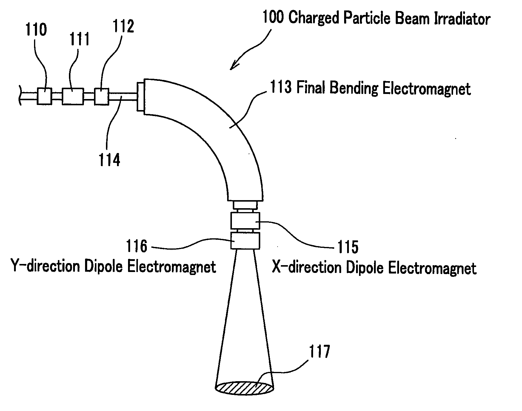
[0023] A description is given, referring to the attached drawings FIG. 1 and FIG. 2, on a charged particle beam irradiator according to the first embodiment of the present invention. FIG. 1 is a drawing illustrating an assembly of an irradiating portion of a charged particle beam irradiator according to the present embodiment. FIG. 2 compares a charged particle beam irradiator according to the present embodiment and a charged particle beam irradiator according to a conventional art, wherein (a) shows the charged particle beam irradiator according to the present embodiment, and (b) shows a charged particle beam irradiator according to the conventional art.
[0024] As illustrated in FIG. 1, in the same way as described in the description of the background art on the charged particle beam irradiator 100, the charged particle beam irradiator 1 includes a beam transfer tube 3 through which a charged particle beam such as a carbon ion beam, etc., travels; quadrupole electromagnets 4, 5, 6 ...
second embodiment
[0028] Next, FIG. 3 illustrates a second embodiment according to the present invention. FIG. 3 compares a rotary gantry according to the present embodiment and a rotary gantry according to a conventional art.
[0029] As illustrated in FIG. 3, the rotary gantry 50 includes a first bending electromagnet 51; a second bending electromagnet 53 which is connected to the first bending electromagnet 51 through a beam transfer tube 52; quadrupole electromagnets 54, 55, 56 installed along the beam transfer tube 52; a third bending electromagnet (final bending electromagnet, hereinafter) 58 which is connected to the second bending electromagnet 53 through a beam transfer tube 57; quadrupole electromagnets 59, 60, 61 installed along the beam transfer tube 57; and a Y-direction dipole electromagnet 62 which is connected to a downstream side end of the final bending electromagnet 58.
[0030] Meanwhile, as illustrated by virtual lines in FIG. 3, a rotary gantry 200 according to the conventional art ...
PUM
 Abstract
Description
Claims
Application Information
PatSnap Eureka turns technology decisions into work you can execute. Powered by our Innovation Knowledge Graph, it runs expert workflows across engineering, life sciences, materials and intellectual property. Get your review-ready output in minutes.


