
Drive unit for medical devices

a technology for driving units and medical devices, applied in piezoelectric/electrostrictive/magnetostrictive devices, medical science, diagnostics, etc., can solve the problems of large construction volume, poor efficiency of gears, and large noise of gears, and achieve cost-effective production, high efficiency, and extremely low noise

Inactive Publication Date: 2008-01-10
ROCHE DIABETES CARE INC
View PDF8 Cites 162 Cited by
  • Summary
  • Abstract
  • Description
  • Claims
  • Application Information

AI Technical Summary

Benefits of technology

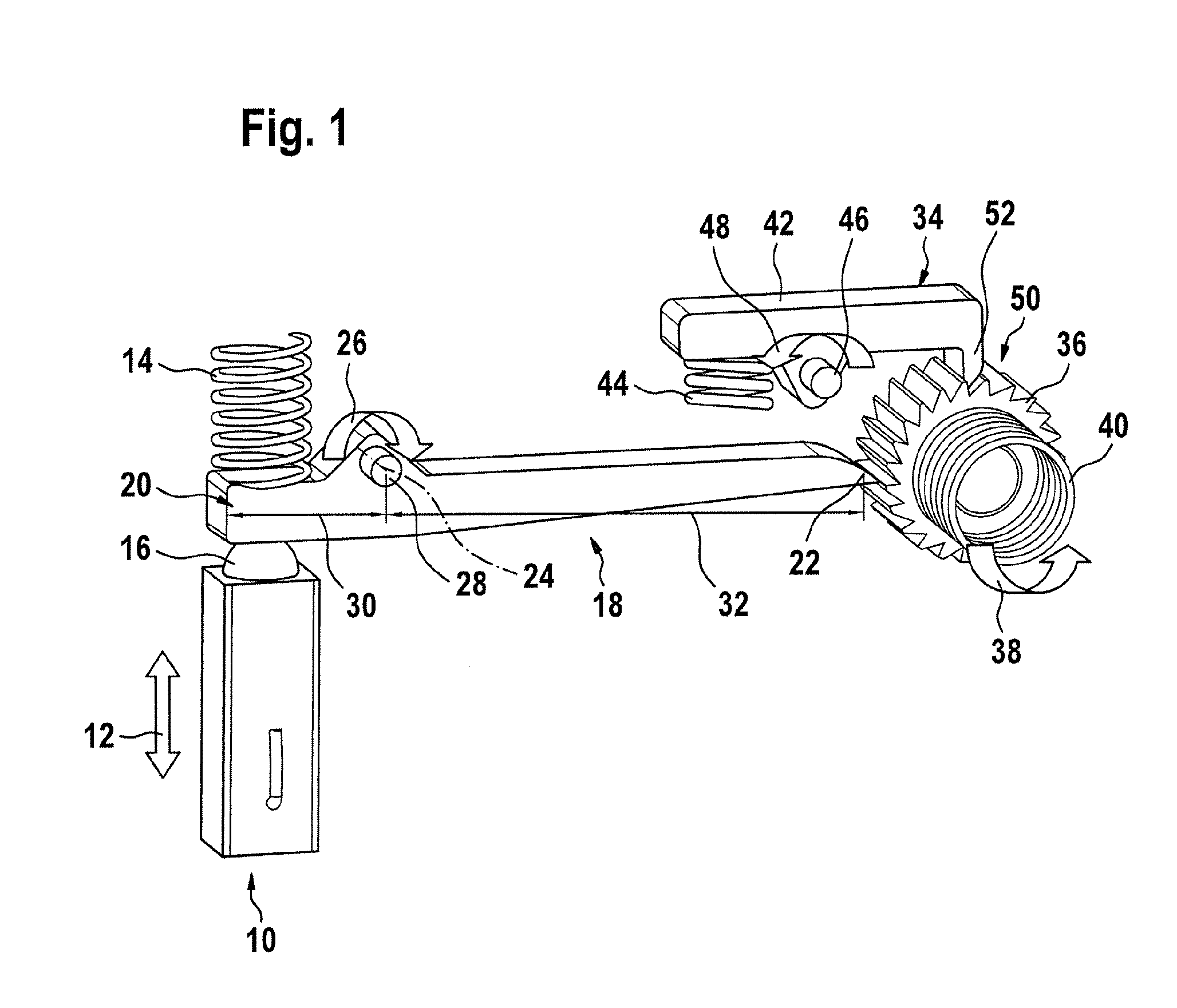
[0010] As a further embodiment of an actuator for a portable measuring device or for an insulin pump, the actuator may also be designed as a micromotor. The micromotor drives a cam of rounded form which has essentially an oval contour. During the rotation of an output shaft of the micromotor, the cam connected fixedly in terms of rotation to the output shaft is set in rotation and contacts a step-up element, capable of being formed, e.g., as a lever, once or several times per revolution, depending on the design variance of the cam. An oscillating movement of a step-up element can thereby be achieved, the latter transmitting a deflection of a lever end caused by the rotational movement of the cam into a nonreturn rotor in accordance with the step-up configuration of the step-up element.
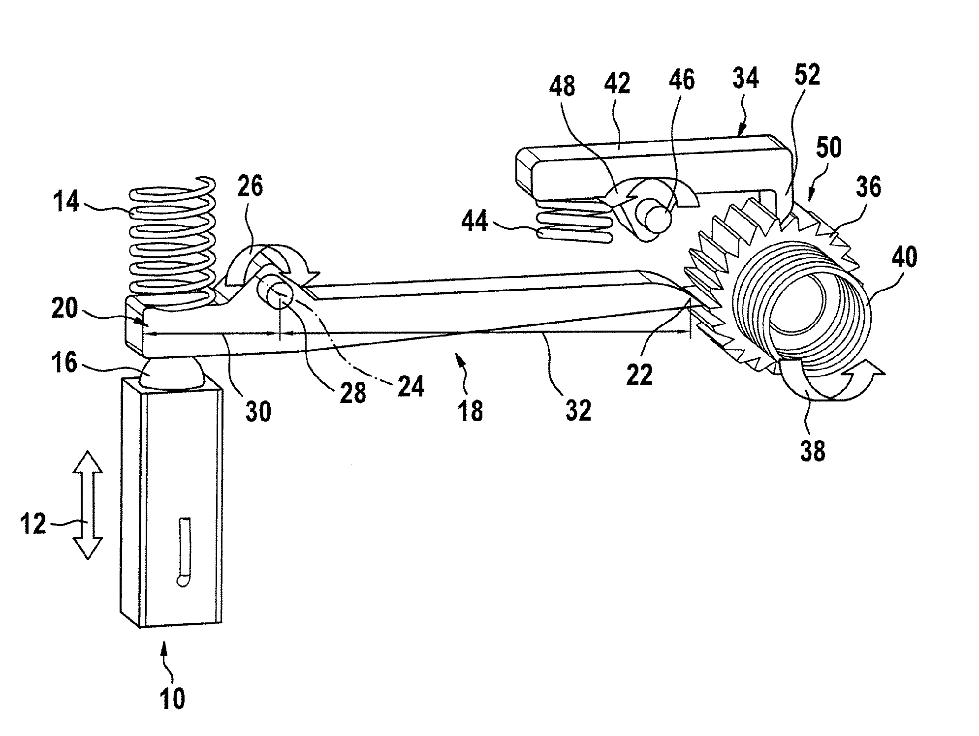
[0016] The step-up element used, e.g., a rotatably mounted lever provided with different lever arms, can be produced by plastic injection molding or by metal stamping. The nonreturn rotor, e.g., a ratchet wheel or a rotor of block-like design guided in guides, and the bearings may likewise be manufactured by plastic injection molding. Consequently, the entire drive unit can be produced cost-effectively, requiring a small amount of construction volume and which produces extremely low noise. Moreover, high levels of efficiency can be achieved by dispensing with a gear comprising a plurality of gearwheels, this being extremely important for the energy balance in medical devices for the recovery of body fluids or in insulin pumps.
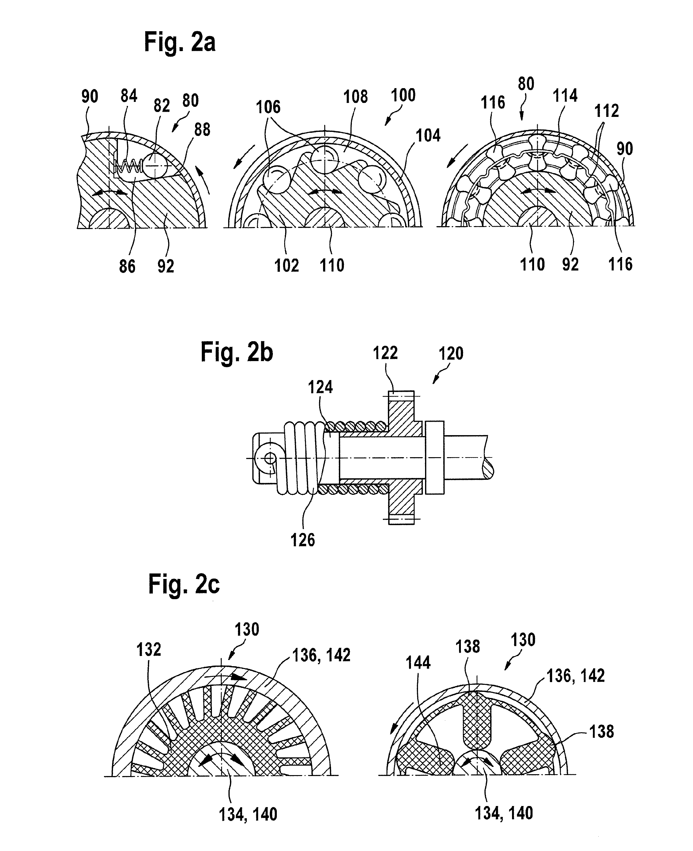
[0017] In a further embodiment according to the invention, the piezoactuator capable of being used within a medical device, e.g., an insulin pump, is activated by means of an alternating voltage of the desired operating frequency. The medical device may be, as well as an insulin pump, a measuring device or analyzer with individual test strips or with a multiplicity of test strips received in a magazine. Furthermore, the disclosed drive unit may be employed in integrated systems with a pricking aid and with an evaluation unit for sample evaluation. In these devices, by means of the disclosed drive unit, system functions, such as the triggering of the pricking operation, the transport and feed of the test strip or the transport of the test strip magazine can be achieved. Also, the disclosed drive unit may be used in straightforward blood sampling devices. The longer the piezocrystal stack of the piezoactuator used is, the greater the working stroke is which can be achieved. The stroke brought about by the length change of the piezocrystal stack (typically 1.5 μm length change per 1 mm of crystal stack length) is transmitted to the coupled, rotatably mounted step-up element. Owing to the step-up ratio set by virtue of the design of the step-up element, the stroke of the lever tip, which acts, e.g., on a nonreturn rotor designed as a ratchet wheel, is increased. During the expansion of the piezoactuator, the ratchet wheel rotates, a nonreturn means enabling this direction of rotation by means of a spring-loaded rotational movement. During the contraction of the piezoactuator in the course of the discharge phase, the step-up element designed as a lever is reset into its initial position by spring force. In this case, the nonreturn means, which comprises a detent pawl and the ratchet wheel, prevents the rotation of the ratchet wheel opposite to the direction of rotation, with the result that a secondary energy storage element can be prestressed.

Problems solved by technology

However, these gears have poor efficiencies, particularly when high step-up ratios are used.
Moreover, these gears produce running noises and take up a large construction volume which, in glucose measuring devices, is available to only a very limited extent for reasons of simple handling.
Moreover, gears with high step-up are mostly provided with metal gearwheels and with exact mountings, thus making them very costly to produce.
Consequently, gears with high step-up, used for prestressing secondary mechanical energy storage elements, undesirably on the one hand considerably enlarge the dimensions of an integrated glucose measuring system and on the other hand considerably increase its production costs.

Method used


Image

  • Drive unit for medical devices
  • Drive unit for medical devices
  • Drive unit for medical devices

Examples


Embodiment Construction

[0037] The embodiments of the present invention described below are not intended to be exhaustive or to limit the invention to the precise forms disclosed in the following detailed description. Rather, the embodiments are chosen and described so that others skilled in the art may appreciate and understand the principles and practices of the present invention.

[0038] Medical devices are understood below to mean those devices which recover a body fluid, e.g., blood, by pricking the skin by means of automatic lancing and taking blood from the extraction point thus made and deliver it to a test strip. The medical devices described in more detail below comprise either one or several test strips which are received in a magazine or a drum. When a medical device of this type is in operation, it is provided with a voltage source, whether it be a battery or an accumulator, via which actuators serving as drives can be supplied with a voltage. The voltage sources constitute long-term electrical...


PUM


Abstract

The invention relates to a drive unit for a medical device such as an insulin pump, lancing device, or test strip magazine. The drive unit comprises an actuator for charging a mechanical energy storage element. The actuator oscillates and executes travel strokes which are transmitted by means of a step-up element to a nonreturn rotor or traveler for prestressing the mechanical energy storage element and driving a movement element.

Description

[0001] This is a continuation application of International Application PCT / EP2006 / 050529, filed Jan. 30, 2006, which claims priority to DE 10 2005 004 498.0, filed Feb. 1, 2005, which are hereby incorporated by reference in their entirety.FIELD OF THE INVENTION BACKGROUND [0002] The present invention relates to a drive unit, in particular a drive unit which is suitable for portable medical devices and with the aid of which movements to be carried out slowly can be automated. [0003] In portable medical devices, e.g., glucose measuring devices, the automatic lancing of a body part and the subsequent automatic recovery of blood from the puncture site formed as a result of the lancing operation play an essential role. To convert electrical energy from a long-term electrical storage element specific to the glucose measuring devices, e.g., accumulators or batteries, into mechanical energy, electric motors or electromagnets are used, according to the prior art. With the aid of these drive ...

Claims


Application Information

Patent Timeline
IPC IPC(8): H02N2/00
CPCA61B5/1411H02N2/10H02N2/043A61B5/150022A61B5/150358A61B5/15107A61B5/15117A61B5/15146
Inventor DECK, FRANK
Owner ROCHE DIABETES CARE INC
Learn More