Hologram Recording and Reproducing Method, Device and System

Inactive Publication Date: 2008-01-10
PIONEER CORP
View PDF1 Cites 16 Cited by
  • Summary
  • Abstract
  • Description
  • Claims
  • Application Information

AI Technical Summary

Benefits of technology

[0014] In consideration thereof, an exemplary object of the present invention is to provide

Problems solved by technology

This thus causes degradation of the read

Method used


Image

  • Hologram Recording and Reproducing Method, Device and System
  • Hologram Recording and Reproducing Method, Device and System
  • Hologram Recording and Reproducing Method, Device and System

Examples


second embodiment

PICKUP OF SECOND EMBODIMENT

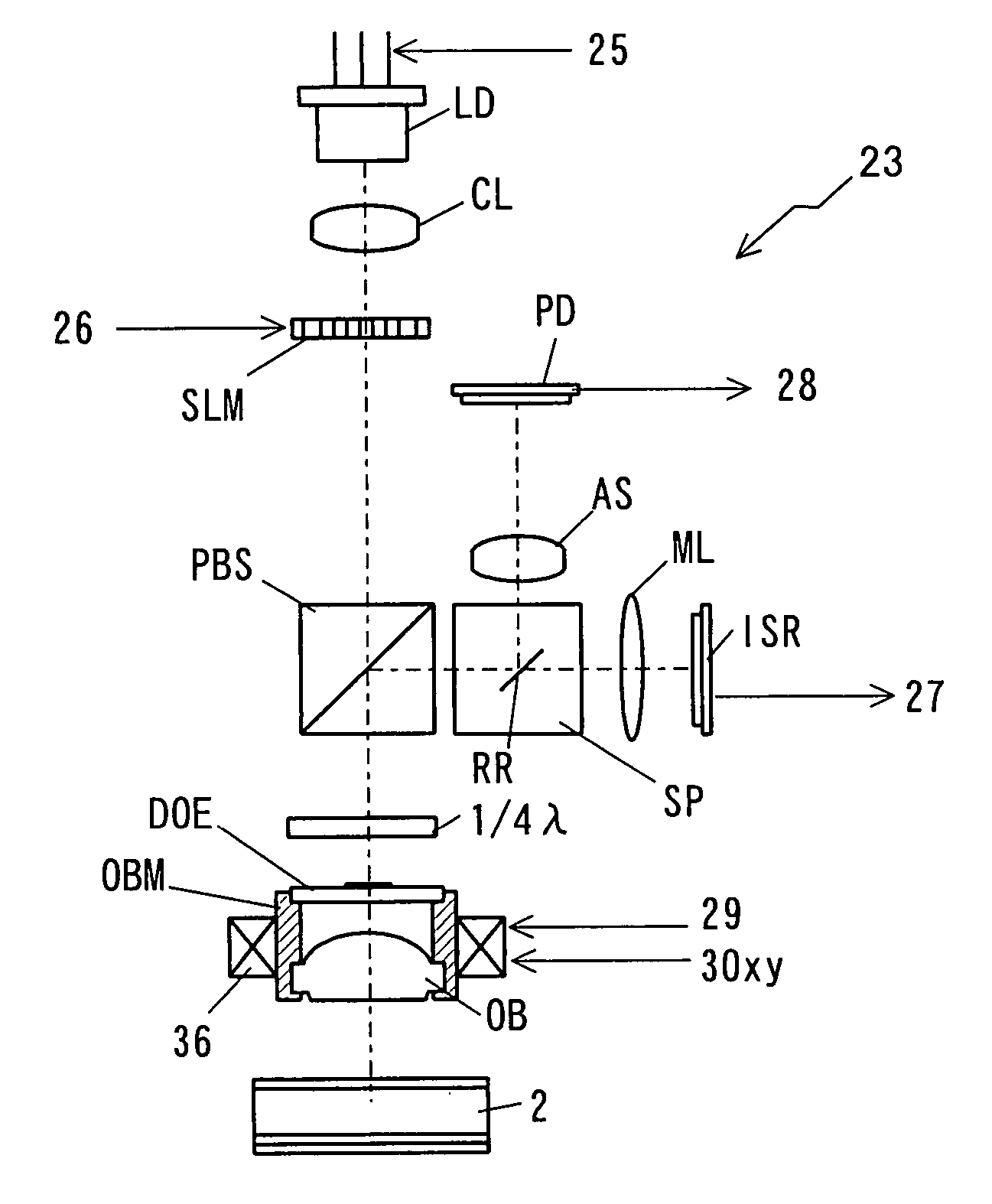
[0131]FIG. 19 shows the configuration of a pickup of a second embodiment.

[0132] The pickup of the second embodiment uses a polarization spatial light modulator PSLM of a reflective-type as an alternative to the spatial light modulator SLM of a through-light type, and an S polarized light from a laser light source LD is directed to the polarization spatial light modulator PSLM via a polarization beam splitter PBS so that its reflected light is used. These are the only differences, and the remaining is the same as the above-described pickup 23.

[0133] As shown in FIG. 20, the polarization spatial light modulator PSLM is a so-called LCOS (Liquid Crystal On Silicon) apparatus in which the are a is divided into a center area A in the vicinity of an optical axis including the optical axis, and a spatial light modulation are a B therearound not including the optical axis. The luminous flux reflected by the spatial light modulation are a B is subjected to modulat...

third embodiment

PICKUP OF THIRD EMBODIMENT

[0138]FIG. 21 shows the configuration of a pickup of a third embodiment.

[0139] The pickup of the third embodiment uses an optical device SDOE for servo detection use and a multi photodetector apparatus CODD for signal detection use as alternatives to the coupling lens AS, the photodetector PD, the reference light separation prism SP, and the image sensor ISR. This is the only difference, and the remaining is the same as the second embodiment.

[0140] As shown in FIG. 22, the optical device SDOE for servo detection use is divided into a center area A including an optical axis and a neighboring are a C therearound not including the optical axis. The center area A is configured as astigmatism generation means, e.g., as a diffraction grating, and a luminous flux passing therethrough suffers from astigmatism. When a light reception surface of a four-way split photodetector is provided in the downstream, a spot with astigmatism is formed. In the neighboring are a...

fourth embodiment

PICKUP OF FOURTH EMBODIMENT

[0144] In the above-described embodiments, using a double focus objective lens, an objective lens, and an objective lens module being a diffractive optical device, a reference light having been passed through the objective lens is so configured as to be gathered at a close-range focal point closer to the objective lens than a long-distance focal point. The optical device with such a function may serve enough if it is disposed on the optical axis of an irradiation optical system. Alternatively, not at a position closer to the objective lens, an optical device having a function of gathering a light at a close-range focal point by an objective lens may be attached to the center are a in a through-light matrix liquid crystal apparatus of the spatial light modulator SLM in the first embodiment of FIG. 10, for example.

[0145] The pickup of the fourth embodiment of FIG. 25 is the same as the pickup 23 of the first embodiment described above except that the object...


PUM


Abstract

A hologram device includes: a support section that keeps hold of, to be able to be attachable and removable, a hologram record carrier including a hologram recording layer stored therein with an optical interference pattern of a coherent signal light and a coherent reference light as a diffraction grating; a light source that generates the coherent reference light; a signal light generation section that is disposed on an optical axis, and generates the signal light by modulating the reference light in accordance with recording information; and an interference section that is disposed on the optical axis, and forms the diffraction grating being the optical interference pattern inside of the hologram recording layer by directing the signal light and the reference light toward the hologram recording layer. The signal light generation section is provided with a spatial light modulator, and the spatial light modulator is configured by a center are a disposed on the optical axis for passing through or reflecting the reference light with no modulation, and a spatial light modulation are a disposed around the center are a for generating the signal light by modulating the reference light in accordance with the recording information. The reference light is propagated on the optical axis, and the signal light is propagated around the reference light with spatial separation therefrom. The interference section includes an objective lens and an optical device, and the objective lens and the optical device gather the reference light at a first focal point, and the signal light at a second focal point being different from the first focal point.

Description

TECHNICAL FIELD [0001] The present invention relates to a record carrier such as an optical disk, optical card and the like with which information recording or information reproduction is optically performed and, more specifically, to a hologram recording and reproducing method, device, and system including a hologram recording layer being information-recordable and information-reproducible by irradiation of luminous fluxes. BACKGROUND ART [0002] For high-density information recording, a hologram capable of high-density recording of two-dimensional data has been receiving attention. This hologram is characterized in that the wavefront of a light carrying recording information is recorded as a change, in volume, of refractive index to a recording medium made of a light-sensitive material such as photorefractive materials and the like. With multiplex recording onto a hologram record carrier, the recording capacity can be dramatically increased. As the configuration, known is a recordi...

Claims


Application Information

Patent Timeline
IPC IPC(8): G03H1/02
CPCG03H1/04G03H1/0402G03H1/0465G03H2223/17G11B2007/13727G11B7/083G11B7/128G11B7/1353G11B7/1374G11B7/0065
Inventor OGASAWARA, MASAKAZUITOH, YOSHIHISATACHIBANA, AKIHIRO
Owner PIONEER CORP
Why Eureka
Try Eureka