Efficient fluorimetric analyzer for single-walled carbon nanotubes

Inactive Publication Date: 2008-01-17
RICE UNIV
View PDF4 Cites 29 Cited by
  • Summary
  • Abstract
  • Description
  • Claims
  • Application Information

AI Technical Summary

Problems solved by technology

As such, a primary hurdle to the widespread application of CNTs, and SWNTs in particular, is ...

Method used


Image

  • Efficient fluorimetric analyzer for single-walled carbon nanotubes
  • Efficient fluorimetric analyzer for single-walled carbon nanotubes
  • Efficient fluorimetric analyzer for single-walled carbon nanotubes

Examples


example 1

[0030] This example serves to illustrate a specific device configuration useful in the compositional analysis of SWNT samples, according to one or more embodiments of the present invention.

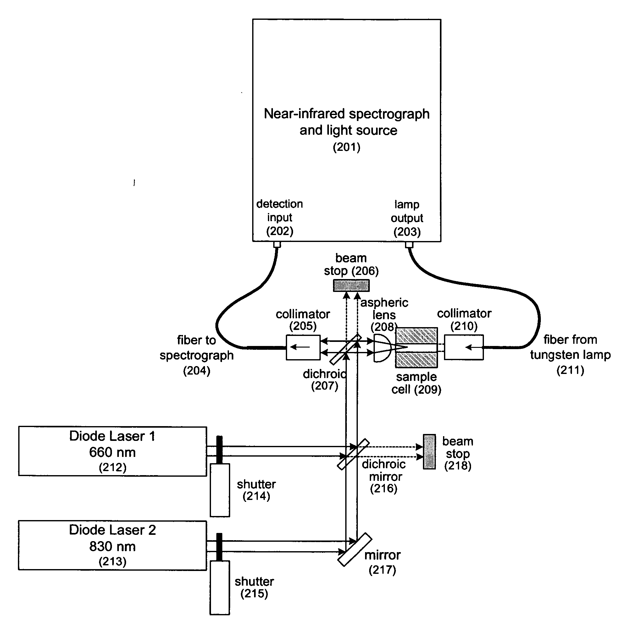
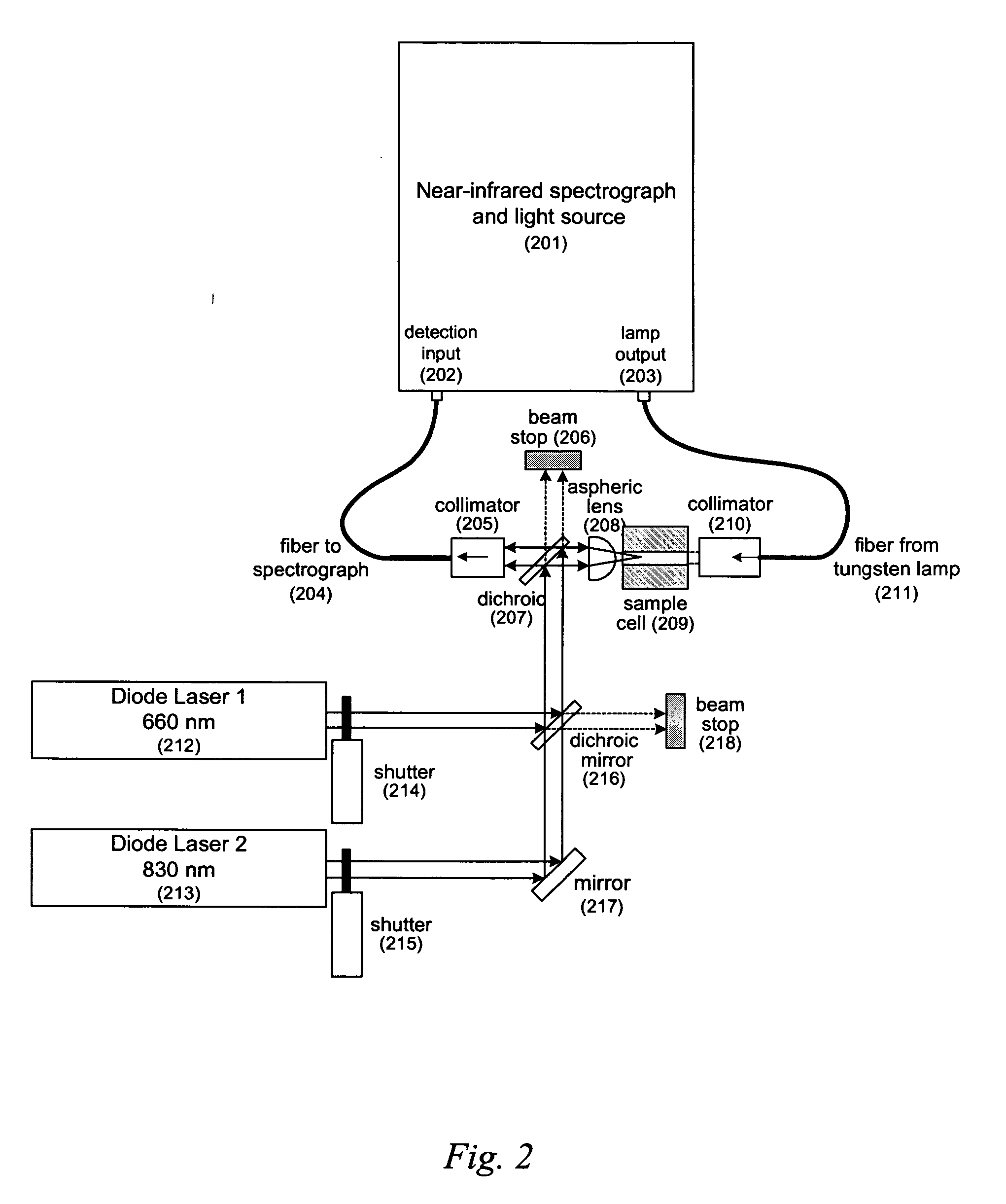
[0031] Two excitation sources irradiate the sample sequentially, with their beams controlled by automated optical shutters. Referring to FIG. 2, these sources are diode lasers 212 and 213 emitting at approximately 660 and 830 nm, respectively. Appropriate dichroic mirrors 216 and 207 reflect the excitation beams into a rectangular sample cell through an aspheric lens 208 of focal length approximately 5 mm. This lens also collects and collimates some of the fluorescence light from the nanotube sample and directs it through a near-infrared transmitting dichroic mirror 207. The fluorescence light is then focused into a multi-mode fiber optic 204 by a collimating lens 205. The fiber optic leads to the entrance slit (detection input 202) of a near-infrared grating spectrograph 201 that has a multichan...

example 2

[0033] This example serves to illustrate a manner in which a SWNT sample can be analyzed by the device described in Example 1.

[0034] A small solid sample (212 (typically ca. 660 nm) is reflected from specialized dichroic mirrors 207 and 216 and focused into the sample cell 209 by an aspherical short focal length lens 208 (ca. 4 mm) to optically excite the nanotubes. A portion of the resulting near-infrared fluorescence is captured by the same lens 208 and directed back toward the dichroic mirror 207 through which it is transmitted. Using collimator 205, this light is then focused into the end of a multimode optical fiber 204 chosen for high transmittance in the near-infrared. The fiber delivers the fluorescence light to the input 202 of a spectrograph / InGaAs photodiode array 201 designed to disperse and detect light in the wavelength range typical of SWNT emission. A control computer records this emission spectrum. The excitation light is then blocked and a broadband near-infrare...

example 3

[0036] This example serves to illustrate a manner in which the computational analysis of the spectral profiles of the SWNT samples can be accomplished.

[0037] The raw emission spectrum (obtained from a device such as that shown in FIG. 2) is transmitted to a controlling computer and then analyzed using custom-written software routines. In this process, the intensities are first corrected for wavelength-dependent variations in the instrument's sensitivity, using a pre-determined response function. The corrected spectrum is transformed from a wavelength scale to an optical frequency scale. Using tabulated, pre-calculated emission profiles for a wide range of nanotube species (see Table 1), the corrected and transformed emission spectrum is simulated (in an iterative nonlinear least-squares fitting process) as a superposition of such profiles. The simulation result gives a set of amplitudes for the various nanotube species. These amplitudes are then multiplied by predetermined sensitiv...


PUM


Abstract

The present invention is directed toward methods and devices for analyzing populations of single-wall carbon nanotubes (SWNTs) on the basis of their fluorescence properties and the comparison of said properties to fluorescence profiles of pre-determined SWNT compositions. Generally, such analyzing yields information about the composition of the SWNTs within said population. Such information includes, for example, the relative abundances of semiconducting SWNTs, the diameter distribution of such SWNTs, and the relative abundances of one or more particular SWNT species—as identified by one or more specific nanotube indices (n,m). The methods and devices of the present invention provide for the analysis of SWNT compositions in a rapid and efficient manner.

Description

RELATED APPLICATIONS [0001] This application claims priority to and benefit of U.S. Provisional Application Ser. No. 60 / 629,447, filed on Nov. 19, 2004, entitled “Efficient Fluorimetric Analyzer for Single-Walled Carbon Nanotubes”, by inventor Weisman et al.[0002] The present invention was made with support from the National Science Foundation, Grant Nos. NSF CHEM-0314270 and EEC-1008007; and the National Aeronautics and Space Administration, Grant No. NASA NNJ04HD88G.FIELD OF THE INVENTION [0003] This invention relates generally to carbon nanotubes, and more specifically to devices and methods for analyzing their fluorescent signatures for the purpose of making compositional determinations. BACKGROUND [0004] Carbon nanotubes (CNTs), comprising multiple concentric shells and termed multi-wall carbon nanotubes (MWNTs), were discovered by Iijima in 1991 [Iijima, Nature 1991, 354, 56-58]. Subsequent to this discovery, single-wall carbon nanotubes (SWNTs), comprising single graphene she...

Claims


Application Information

Patent Timeline
IPC IPC(8): G01N21/64
CPCG01N21/6402G01N2021/6417G01N21/645
Inventor WEISMAN, R. BRUCEBACHILO, SERGEI M.ROCHA, JOHN-DAVID R.CASEY, JOHN P.
Owner RICE UNIV
Why Eureka
Try Eureka