Vehicle Abnormality Detection Method and Device Thereof and Sensor Unit Thereof

Inactive Publication Date: 2008-01-24
YOKOHAMA RUBBER CO LTD
View PDF85 Cites 26 Cited by
  • Summary
  • Abstract
  • Description
  • Claims
  • Application Information

AI Technical Summary

Benefits of technology

[0069] According to the vehicle abnormality detection method and the abnormality detection device of the present invention, heat is generated by friction between the tire body and road surface during running of the vehicle, and the tire body temperature and the air temperature within tire being the first temperature rise. However, when there is generated a high temperature ascribable to frictional heat in the vehicle bearing mechanism section or vehicle brake mechanism section due to maladjustment of the vehicle bearing mechanism section or vehicle brake mechanism section, the second temperature related to the vehicle bearing mechanism section temperature or vehicle brake mechanism section temperature rises significantly higher than the first temperature. Therefore, with respe

Problems solved by technology

Conventionally, when an abnormality occurs in tire air pressure during running of a vehicle, this may cause an accident; there have thus been developed devices automatically monitoring the tire air pressure to raise an alarm when an abnormality occurs in the tire air pressure.
When this device is used, the driver can perceive an abnormal phenomenon such as decrease or increase of the tire pressure at any time before running or during running and early perform a tire inspection or emergency measure.
Also, when the brake of the tire is abnormally heated, this may lower the braking force, causing an accident; there have thus been developed devices automatically monitoring a temperature of a tire brake and raising an alarm when an abnormality occurs in brake temperature.
Generally, in a leading drum brake used often in trucks or buses, if adjustment is erroneously made, even when the brake is not activated, the brake shoe is opened due to self servo effect that the brake has in principle, thus generating frictional heat.
Also, in bearings used in an axle bearing

Method used


Image

  • Vehicle Abnormality Detection Method and Device Thereof and Sensor Unit Thereof
  • Vehicle Abnormality Detection Method and Device Thereof and Sensor Unit Thereof
  • Vehicle Abnormality Detection Method and Device Thereof and Sensor Unit Thereof

Examples


second embodiment

[0149] the present invention will now be described.

[0150] The device configuration according to the second embodiment is approximately similar to that of the first embodiment described above. The difference lies in that according to the second embodiment, when first temperature T1 reaches a predetermined threshold temperature Tth1 or more, an alarm is raised and also, when second temperature T2 is a predetermined threshold temperature Tth2 or more, an alarm is raised.

[0151] According to the present embodiment, the threshold temperature Tth1 is set to, for example, 150° C. and an alarm is raised before the first temperature T1 reaches solder melting temperature in the printed circuit board 103 or the like. Also, the threshold temperature Tth2 is set to, for example, 100° C. and an alarm is raised before fire occurs.

third embodiment

[0152] the present invention will now be described.

[0153]FIG. 19 is a cross-sectional view illustrating a valve stem according to the third embodiment of the present invention. According to the present embodiment, a valve stem formed integrally with a sensor unit is constructed. More specifically, the valve stem 70 of the present embodiment has a chamber 71 and an isolated chamber 72 adjacent to the chamber 71; in the interior of the isolated chamber 72, there is contained a unit body including a printed circuit board 103A having disposed therein electric components and a battery 160; a pressure sensing element 111 is fit and glued to a through hole 73 arranged in a dividing wall between the chamber 71 and the isolated chamber 72 in such a manner that air leakage does not occur.

[0154] In one end of the chamber 71 of the valve stem 70, similarly to an ordinary valve stem, there is arranged a valve core 70a; the other end of the valve stem 70 is inserted into a through hole of the ri...

fourth embodiment

[0158] the present invention will now be described.

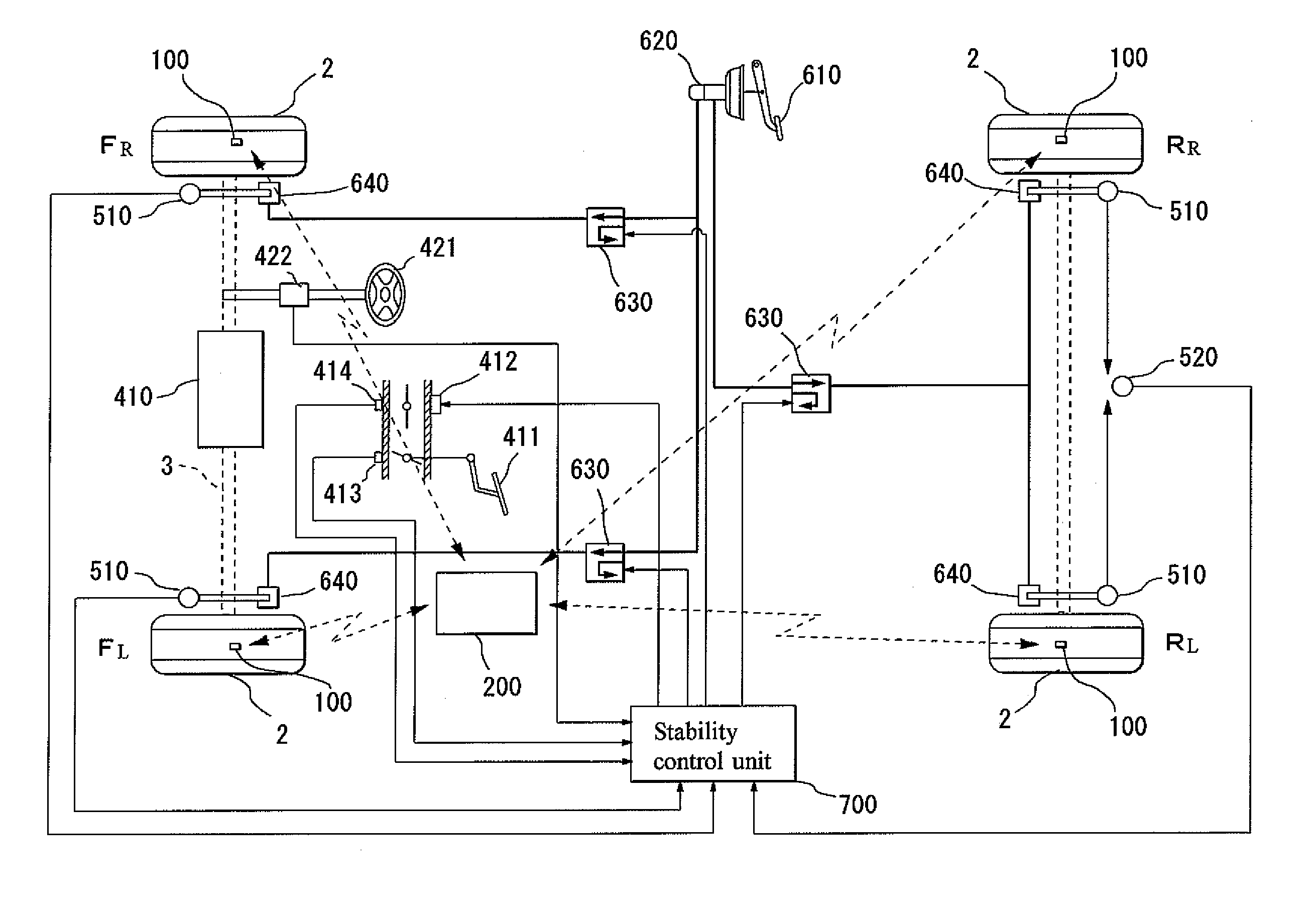
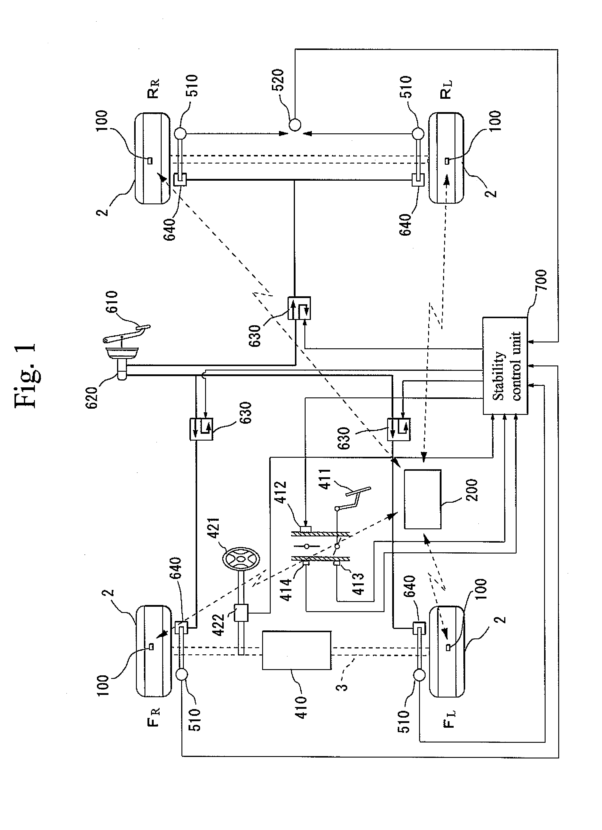
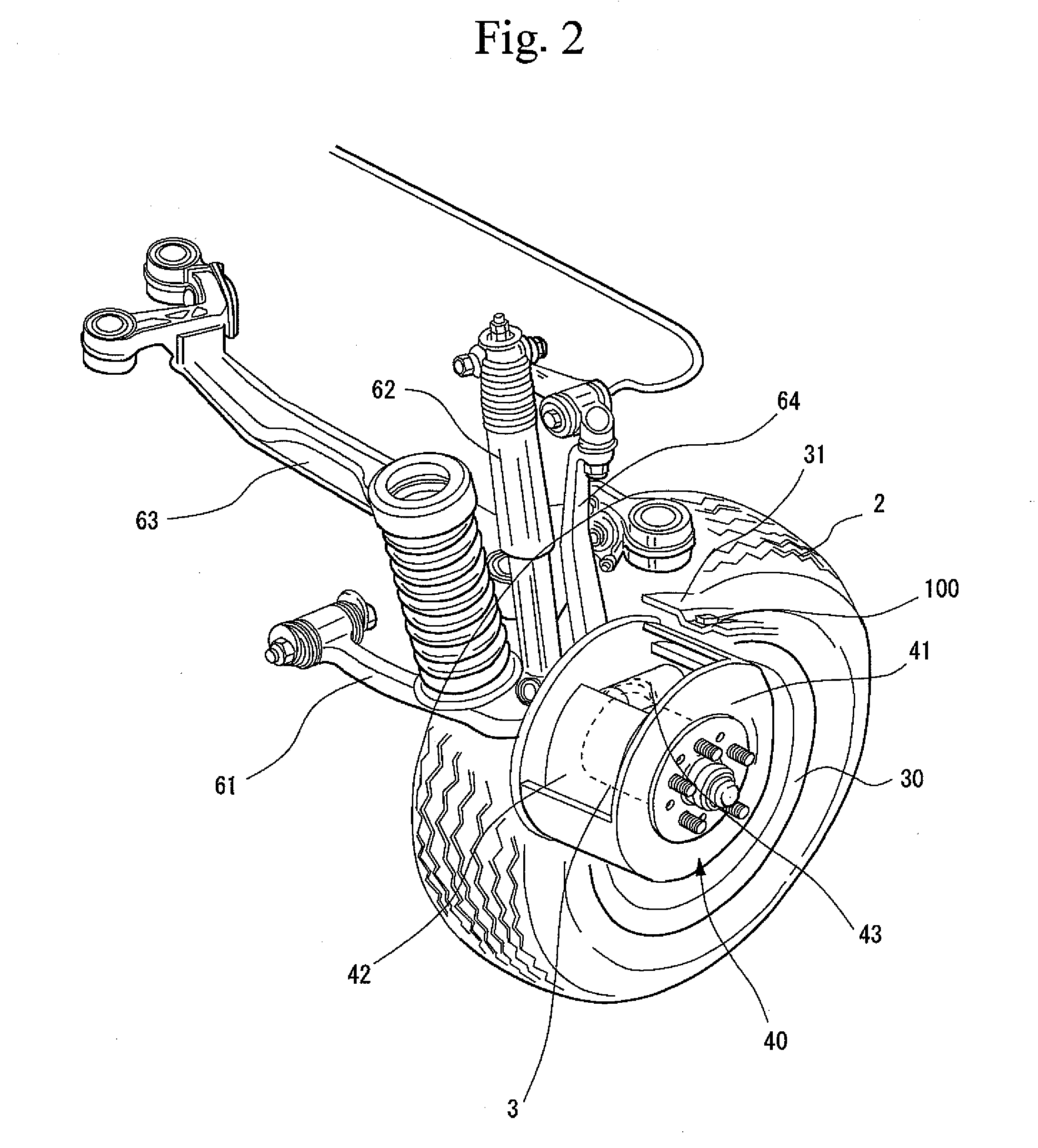
[0159]FIG. 20 is a view for explaining the overall configuration of a vehicle abnormality detection device according to the fourth embodiment of the present invention; FIG. 21 is a block diagram illustrating an electrical circuit of a first sensor unit according to the fourth embodiment of the present invention; FIG. 22 is a block diagram illustrating an electrical circuit of a second sensor unit according to the fourth embodiment of the present invention; FIG. 23 is a view for explaining the location of placement of the first and second sensor units according to the fourth embodiment of the present invention. In these drawings, the same reference numerals are applied to constituent parts corresponding to the first embodiment described above, and an explanation thereof is omitted. The difference between the fourth embodiment and the first embodiment lies in that according to the fourth embodiment, instead of the sensor unit 100 of t...


PUM


Abstract

There is provided a vehicle abnormality detection method detecting an abnormal state in which a high temperature occurs due to maladjustment of a vehicle bearing mechanism section or vehicle brake mechanism section, and a device thereof and a sensor unit thereof. By use of the sensor unit 100 mounted in a rim 31, an air temperature within a tire 2 is sensed as a first temperature and a temperature (second temperature) of the rim 31 is sensed as a temperature related to at least one of a temperature of the vehicle bearing mechanism section and a temperature of the vehicle brake mechanism section 40. Then a temperature difference between the first and second temperatures is calculated and when the temperature difference is a predetermined value or more, it is determined that an abnormality has occurred in the vehicle bearing mechanism section or vehicle brake mechanism section 40. The abnormality is thus detected.

Description

TECHNICAL FIELD [0001] The present invention relates to a vehicle abnormality detection method for detecting an abnormality of a vehicle tire and more particularly, of an axle bearing or a brake, and to a device thereof and a sensor unit thereof. BACKGROUND ART [0002] Conventionally, when an abnormality occurs in tire air pressure during running of a vehicle, this may cause an accident; there have thus been developed devices automatically monitoring the tire air pressure to raise an alarm when an abnormality occurs in the tire air pressure. For example, a device disclosed in Japanese Patent Publication No. 2003-121281 (Patent Document 1) includes a wheel for mounting a tire, a tire pressure sensing unit and a display unit. The tire pressure sensing unit is arranged in a sensing unit housing slot formed at a predetermined position of a corresponding surface abutting on a tubeless tire of a wheel. Information obtained by sensing a tire pressure is outputted to the display unit as a si...

Claims


Application Information

Patent Timeline
IPC IPC(8): G01K1/14
CPCB60C23/0408G01K13/08B60C23/0498B60C23/20B60G2204/115B60G2400/70B60G2600/08B60G2600/082B60G2800/80B60T17/22B60W30/02B60W50/0205B60W2510/0604B60W2510/184F16D2066/001G01K1/14G01K13/00B60C23/0496
Inventor SHIMURA, KAZUHIRO
Owner YOKOHAMA RUBBER CO LTD
Why Eureka
Try Eureka