Perimeter security system

a security system and perimeter technology, applied in the field of perimeter security systems, can solve the problems of inaccurate readings, complicated tracking intrusions, and wireless security or intruder detection systems

Inactive Publication Date: 2008-01-24
INTELLIGENT AUTOMATION
View PDF17 Cites 34 Cited by
  • Summary
  • Abstract
  • Description
  • Claims
  • Application Information

AI Technical Summary

Benefits of technology

[0009]The security system of the present invention can monitor physical intrusions into an area, either indoors or outdoors, by human or other intruders and report the intrusion and its nature to a user. Some of the uses for the security system of the present invention, due to its flexible and adaptable nature, include perimeter sensing for detecting humans crossing a particular perimeter, bread crumbs fun

Problems solved by technology

In the past, wireless security or intruder detection systems have had the disadvantages of being complicated with respect to tracking an intrusion, of providing inac

Method used


Image

  • Perimeter security system
  • Perimeter security system
  • Perimeter security system

Examples


Embodiment Construction

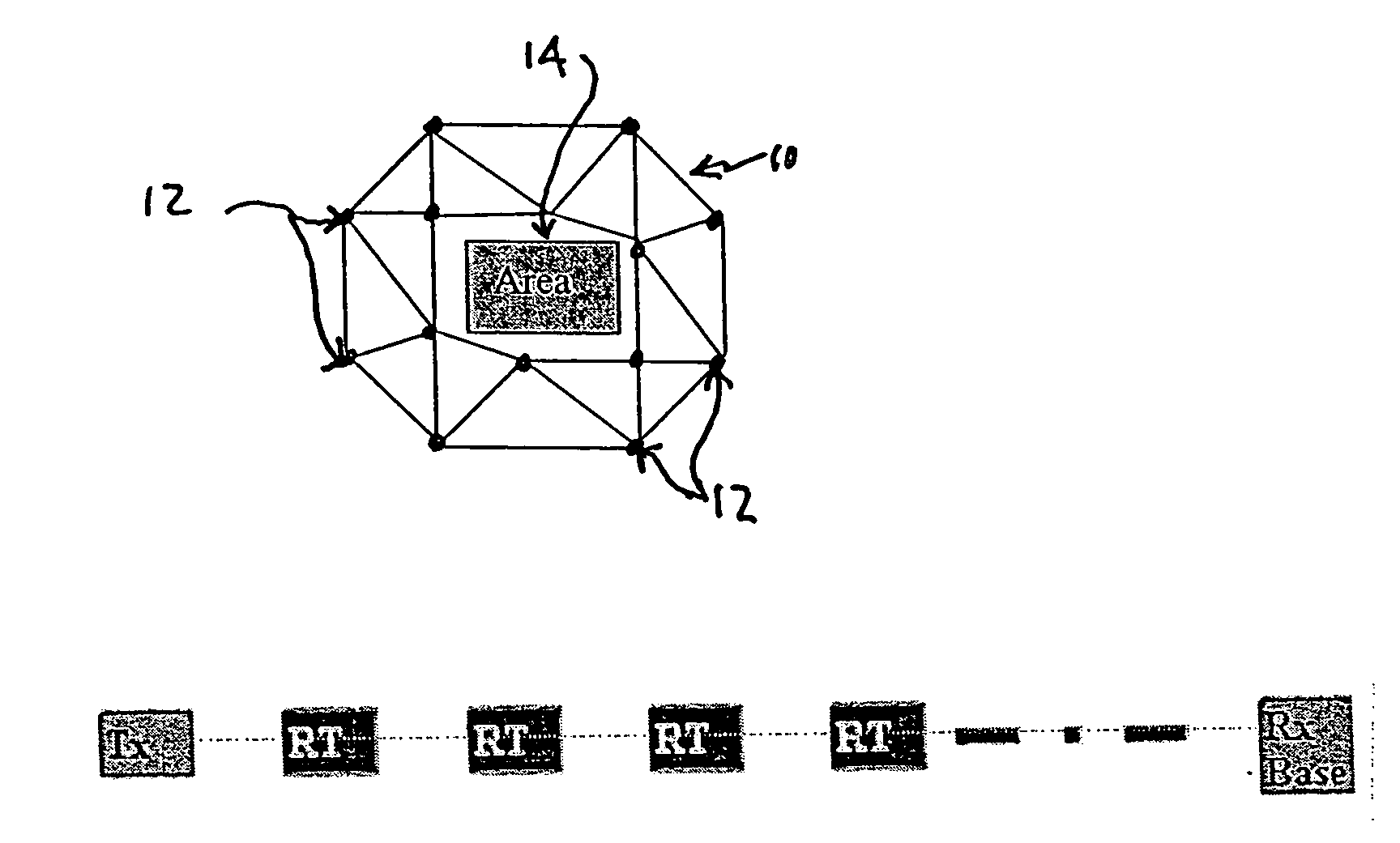
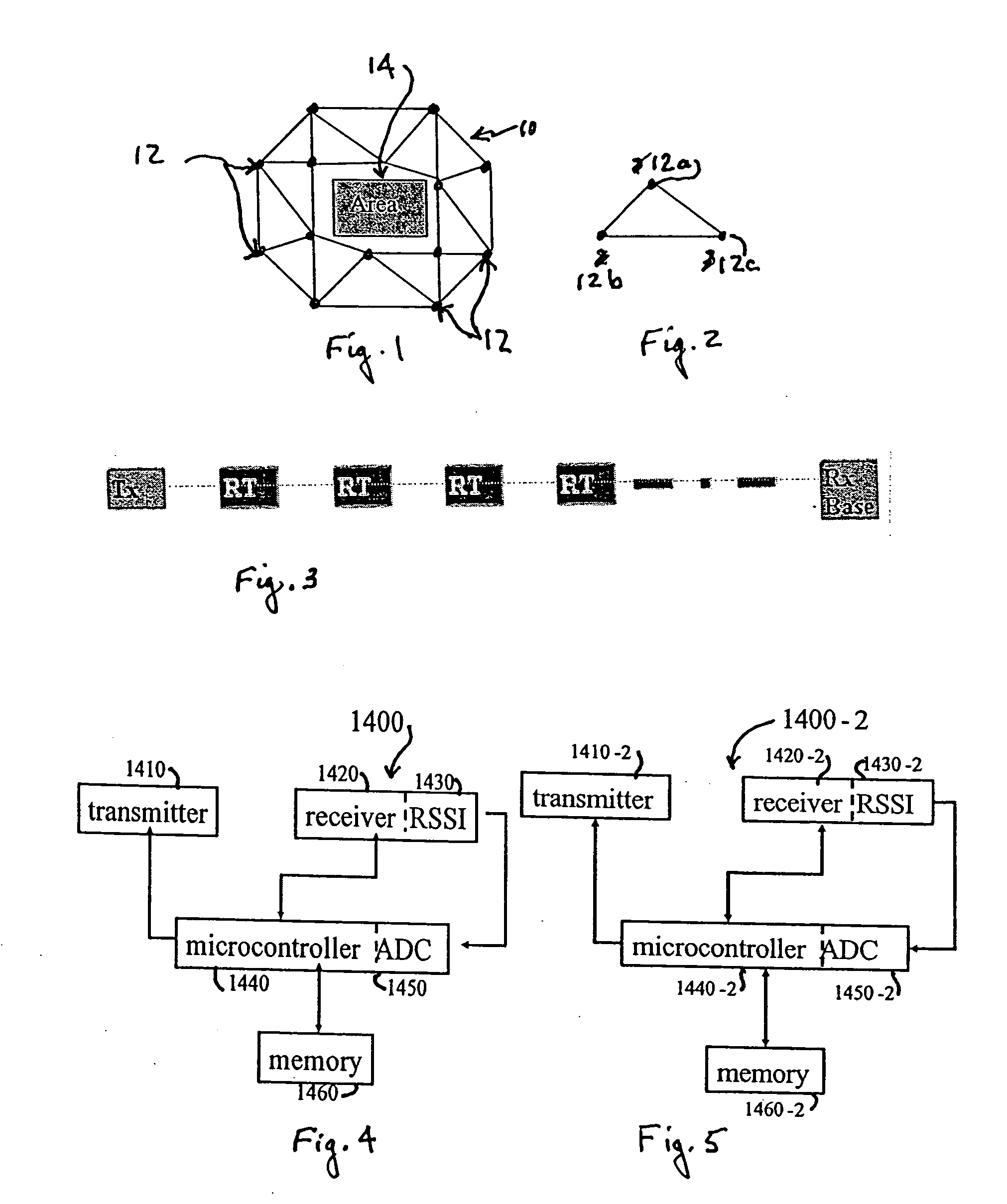
[0020]An exemplary embodiment of the present invention is shown in FIGS. 1 and 2 with FIG. 1 illustrating a simple relaying network 10 of radio units 12 disposed at nodes in a triangular arrangement as illustrated in FIG. 2 to form the “backbone” for relaying information while acting as sensors arranged to form a perimeter for a monitored area 14. The radio units 12 shown in FIG. 1 are essentially arranged in triangular relationships as shown in FIG. 2 where the radio units of a triangle are illustrated as 12a, 12b and 12c. As shown simplistically in FIG. 3, a simple perimeter, as opposed to the triangular arrangement shown in FIGS. 1 and 2, is formed of a transmitter Tx, relay links or nodes RT and a receiver base Rx such as a PDA or computer. An intrusion, such as a human crossing in the line of sight between the relay links and the receiver base would be detected and sent to a monitoring or base station. The security system includes a network of narrow band radio units interfaced...


PUM


Abstract

A security system for detecting physical intrusion in a monitored area including a plurality of radio units arranged in a network around the monitored area to determine received signal strength and pass variations thereof through the radio units to a base station.

Description

BACKGROUND OF THE INVENTION[0001]1. Field of the Invention[0002]The present invention relates to wireless security systems and, more particularly, to wireless security systems for detecting physical intrusions or movements in a monitored area or perimeter and reporting any intrusions and / or movements.[0003]2. Description of the Prior Art[0004]There is a great need for wireless security systems to detect physical intrusions into monitored areas by human or other intruders and report the intrusion and its nature. In the past, wireless security or intruder detection systems have had the disadvantages of being complicated with respect to tracking an intrusion, of providing inaccurate readings in the presence of noise or interference and of utilizing expensive equipment not easily arranged to form a perimeter around an area to be monitored. U.S. Pat. No. 4,213,122 to Rotman et al, U.S. Pat. No. 4,224,607 to Poirier et al, U.S. Pat. No. 6,424,259 to Gagnon, U.S. Pat. No. 6,614,384 to Hall...

Claims


Application Information

Patent Timeline
IPC IPC(8): G08B13/18
CPCG01S7/003G01S13/003G08B13/2491G08B13/187G08B13/126
Inventor VAN DOORN, ERICRANGASWAMY, SENDIL
Owner INTELLIGENT AUTOMATION
Why Eureka
Try Eureka