Multiple-body-configuration multimedia and smartphone multifunction wireless devices

a multi-body configuration, wireless device technology, applied in the structural forms of radiating elements, substantially flat resonant elements, resonance antennas, etc., can solve the problems of reducing the number of devices. , to achieve the effect of enhancing computing capabilities and efficient integration of musi

Active Publication Date: 2008-01-24
FRACTUS
View PDF99 Cites 90 Cited by
  • Summary
  • Abstract
  • Description
  • Claims
  • Application Information

AI Technical Summary

Benefits of technology

[0036]One problem to be solved by the present invention is therefore to provide an enhanced wireless connectivity. Another effect of the invention is to provide antenna design parameters that tend to optimize the efficiency of an antenna for a MFWD device while observing the constraints of small device size and enhanced performance characteristics.
[0037]A multifunction wireless device having at least one of multimedia functionality and smartphone functionality, the multifunction wireless device including an upper body and a lower body, the upper body and the lower body being adapted to move relative to each other in at least one of a clamshell, a slide, and a twist manner. The multifunction wireless device further includes an antenna system disposed within at least one of the upper body and the lower body and having a shape with a level of complexity of an antenna contour defined by complexity factors F21 having a value of at least 1.05 and not greater than 1.80 and F32 having a value of at least 1.10 and not greater than 1.90.
[0038]A multifunction wireless device having at least one of multimedia and smartphone functionality, the multifunction wireless device including a microprocessor and operating system adapted to permit running of word-processing, spreadsheet, and slide software applications, and at least one memory interoperably coupled to the microprocessor, the at least one memory having a total capacity of at least 1 GB. The multifunction wireless device further includes an antenna system having a shape with a level of complexity of an antenna contour defined by complexity factor F21 having a value of at least 1.05 and not greater than 1.80 and by complexity factor F32 having a value of at least 1.10 and not greater than 1.90.
[0039]A multifunction wireless device having at least one of multimedia and smartphone functionality, the multifunction wireless device including a receiver of at least one of analog and digital sound signals, an image recording system comprising at least one of an image sensor having at least 2 Megapixels in size, a flash light, an optical zoom, and a digital zoom, and data storage means having a capacity of at least 1 GB. The multifunction wireless device further includes an antenna system having a shape with a level of complexity of an antenna contour defined by complexity factor F21 having a value of at least 1.05 and not greater than 1.80 and by complexity factor F32 having a value of at least 1.10 and not greater than 1.90.
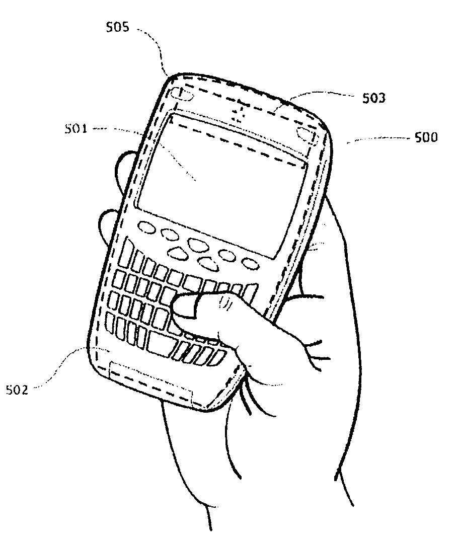
[0040]The present invention is related to a portable multifunction wireless device (MFWD) and in particular to a handheld multifunction wireless device. In some embodiments, the MFWD will take the form of a handheld multimedia terminal (MMT) including wireless connectivity to mobile networks. In some embodiments, the MFWD will take the form of a handheld device combining personal computer capabilities, mobile data and voice services into a single unit (smartphone, SMRT), while in others the MFWD will combine both multimedia and smartphone capabilities (MMT+SMRT).
[0041]It is an object of the present invention to provide wireless connectivity to an MFWD that takes the form of a handheld multimedia terminal (MMT). In some embodiments, the MMT will include means to reproduce digital music and sound signals, preferably in a data compressed format such as for instance a MPEG standard such as MP3 (MPEG3) or MP4 (MPEG4). In some embodiments, the MMT will include a digital camera to record still (pictures, photos) and / or moving images (video), combined with a microphone or microphone system to record live sound and convert it to a digital compressed format. The present invention will be particularly suitable for those MMT embodiments combining both music and image capabilities, by providing means to efficiently integrate music, images, live video and sound recording and playing into a very small, compact and lightweight handheld device.

Problems solved by technology

A slim MFWD should be mechanically stable, mechanical stability being more difficult to achieve in slim devices.
Here radiation into the horizontal plane is usually less desired.
Furthermore, an antenna has to be integrated into a device such as MFWD such that an appropriate antenna may be integrated therein which puts constraints upon the mechanical fit, the electrical fit and the assembly fit of the antenna within the device.
As can be imagined, a simultaneous improvement of all features described above is a major challenge for persons skilled in the art.
A typical exemplary design problem is the generally uniform line of thinking that due to the limits of diffraction, a substantial increase in gain and directivity can only be achieved through an increase in the antenna size.
This, however, is not always practical since portable device users need to have the freedom to move and change direction with respect to a base station without losing coverage and, therefore, losing the wireless connection.
While it might appear desirable to provide an antenna with a uniform radiation pattern (sphere-like) for voice calls such a pattern turns out to have substantial drawbacks in terms of a desired low specific absorption rate since it sometimes leads to an increased absorption of radiation within the hand and the head of the user during a voice phone call.
In every MFWD, the choice of the antenna, its placement in the device and its interaction with the surrounding elements of the device will have an impact on the overall wireless connection performance making its selection non-trivial and subject to constraints due to particular target use, user and market segments for every device.
This concentration leads to a high quality factor which, however, leads to a smaller bandwidth.
Further, such a high concentration of electromagnetic field in the material leads to inherent electrical losses.
Such additional resonating physical structures occupy additional space which then increases the size of the antenna.
It is therefore particularly difficult to build antennas which are both small and multi-band at the same time.
Therefore, many small antennas have great difficulty in achieving a desired large bandwidth.
Further, those two antenna portions may not be provided too close together since, due to electric coupling between the two elements, the merging of the two bands into a single band is not achieved, but rather splitting the resonant spectrum into independent sub-bands which is not acceptable for meeting the requirements of wireless communication standards.
This width, however, requires additional space which further shows that small broadband antennas are difficult to achieve.
It is known to achieve a broadband operation with parasitic elements which, however, require additional space.
Such parasitic elements may also not be placed too close to other antenna portions since this will also lead to splitting the resonant spectrum into multiple sub-bands.
However patch antennas, are unfortunately known to have poor gain and narrow bandwidths, typically in the range of 1% to 5% which is unsuitable for coverage of certain bands such as the UMTS band.
Although it is known that the bandwidth may be increased by changing the separation between the patch and its ground plane, this then destroys the advantage of patch antennas being flat.
This also leads to a distortion of the radiating pattern, for instance, due to surface wave effects.
As mentioned above, such high dielectric materials tend to reduce the bandwidth which is then disadvantageous for patch antennas.
Such materials also generally increase losses.
Further difficulties in antenna design occur when trying to build multi-band antennas.
Therefore, it is difficult to simply take a working antenna and try to add one more band by just adding one more antenna portion.
All previously achieved optimizations for already established frequency bands are lost by such an approach.
Such coupling raises the issue of isolation between the different radio frequency devices, which are both connected to the same antenna.
Isolation of this type is a very difficult task.
All these different design problems of antennas may only be solved in the design of the geometry of the antenna.
Nevertheless, it is practically impossible to identify at least one or two geometric features which affect only one or two of the above-mentioned antenna characteristics.
Any change to the antenna geometry may harm more than it helps without knowing in advance how and why it happens or how it can be avoided.

Method used


Image

  • Multiple-body-configuration multimedia and smartphone multifunction wireless devices
  • Multiple-body-configuration multimedia and smartphone multifunction wireless devices
  • Multiple-body-configuration multimedia and smartphone multifunction wireless devices

Examples


illustration examples

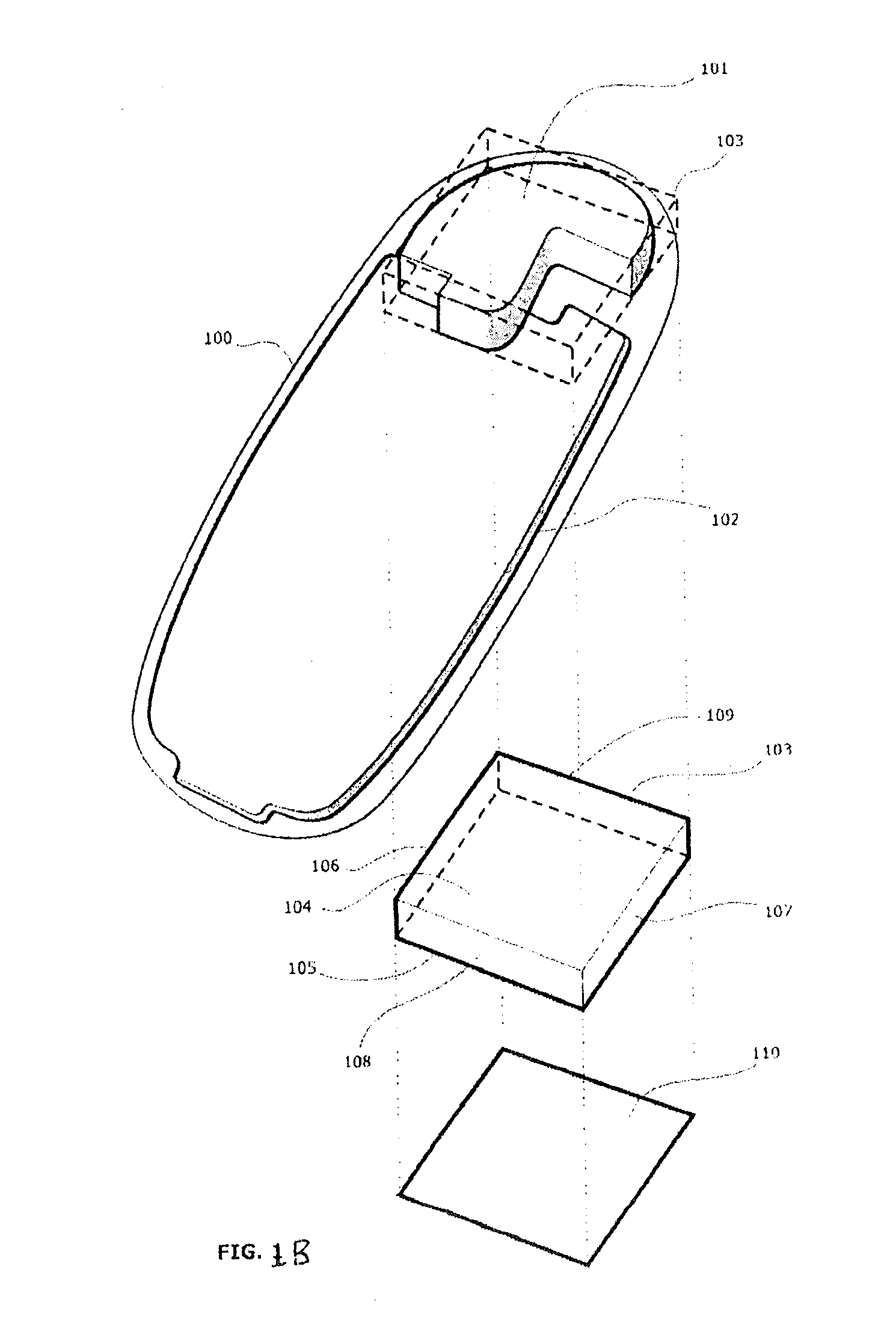
[0225]Referring now to FIG. 1B, there is shown a perspective view of a MFWD 100 comprising, in this particular example, only one body. A volume of space 101 within the MFWD 100 is made available for the integration of an antenna system. The MFWD 100 also comprises a multilayer PCB that includes feeding means and / or grounding means. A layer 102 of the PCB serves as a ground plane of the antenna system.

[0226]An antenna box 103 is obtained as a minimum-sized parallelepiped that completely encloses the volume 101. In this example, the antenna box 103 has rectangular faces 104-109. According to the present invention as described above, the structure of the antenna system comes into contact with each of the six (6) faces of the antenna box 104-109 in at least one point of each face. Moreover, the antenna system of MFWD 100 has no portion that extends outside the antenna box 103.

[0227]An antenna rectangle 110 is obtained as the orthogonal projection of the antenna box 103 along the normal ...


PUM


Abstract

A multifunction wireless device having at least one of multimedia functionality and smartphone functionality, the multifunction wireless device including an upper body and a lower body, the upper body and the lower body being adapted to move relative to each other in at least one of a clamshell, a slide, and a twist manner. The multifunction wireless device further includes an antenna system disposed within at least one of the upper body and the lower body and having a shape with a level of complexity of an antenna contour defined by complexity factors F21 having a value of at least 1.05 and not greater than 1.80 and F32 having a value of at least 1.10 and not greater than 1.90.

Description

CROSS-REFERENCE TO RELATED APPLICATIONS[0001]This patent application claims priority from, and incorporates by reference the entire disclosure of U.S. Provisional Patent Application No. 60 / 831,544, filed Jul. 18, 2006, and U.S. Provisional Patent Application No. 60 / 856,410, filed Nov. 3, 2006. This patent application further claims priority from, and incorporates by reference the entire disclosure of European Patent Application No. EP 06117352.2, filed Jul. 18, 2006.TECHNICAL FIELD[0002]The present invention relates to a multifunction wireless device (MFWD), and, more particularly, but not by way of limitation, to a multifunction wireless device and antenna designs thereof combining into a single unit mobile data and voice services with at least one of multimedia capabilities (multimedia terminal (MMT) and personal computer capabilities, (i.e., smartphone) or with both MMT and smartphone (SMRT) capabilities (MMT+SMRT).HISTORY OF RELATED ART[0003]MFWDs are usually individually adapte...

Claims


Application Information

Patent Timeline
Patent Type & Authority Applications(United States)
IPC IPC(8): H01Q1/24H01Q5/371H01Q5/40
CPCH01Q1/243H01Q1/36H01Q5/40H01Q9/0421H01Q5/371H01Q9/0407
Inventor BALIARDA, CARLES PUENTEMUMBRU, JOSEPILARIO, JORDI
Owner FRACTUS
Why Eureka
Try Eureka