Shape reconstruction using x-ray images

a technology of x-ray images and shape reconstruction, applied in the field of medical imaging, can solve the problems of increasing the radiation load on the patient, high cost of devices, and system lack of the required accuracy for the respective patient to be treated, and achieve the effect of suppressing spurious edges and greatly speeding up the extraction process

Active Publication Date: 2008-01-24
BRAINLAB +1
View PDF6 Cites 26 Cited by
  • Summary
  • Abstract
  • Description
  • Claims
  • Application Information

AI Technical Summary

Benefits of technology

[0021] A standard implementation of the Canny edge detector with hysteresis as described in Canny J.: A computational approach to edge detection. IEEE T Pattern Anal, Vol. 8, No. 6, (1986) 679-698, which is hereby incorporated by reference, can be used to find the edge pixels of the considered bone structure from the input images. To suppress spurious edges, Gaussian convolution kernel with large width can be used to first smooth the input images. The detected edge pixels can be further processed using the knowledge about the X-ray machine. A detected edge pixel whose intensity is below some threshold or whose position is of a certain distance away from the image center can be eliminated.
[0022] For the fast extraction of a smooth apparent contour from a given surface model, the approach introduced by Hertzmann and Zorin, described in Hertzmann A. and Zorin D.: Illustrating smooth surfaces. In SIGGRAPH, (2000), 517-526, which is hereby incorporated by reference, can be used. This approach first constructs a dual representation of the given surface mesh in a four-dimensional (4D) space based on the position and tangent planes of every vertex. The focal point's dual (a plane in 4D) intersects with the mesh triangle's dual. Beforehand, the approach normalizes the dual vertices using the I∞ norm so that the vertices end up on one of the unit hypercube's sides. This reduces the problem to intersecting the triangles on a hypercube's side with the focal point's dual plane, i.e., to intersect triangles in eight 3D unit cubes (the eight hypercube sides) with a plane. By using Octree for each hypercube side, the extraction process can be greatly sped up. An example is given in FIG. 4.

Problems solved by technology

A disadvantage of methods in which tomographs (CT, MR) or X-ray images are produced specifically for navigation within the framework of treatment is that it increases a radiation load on the patient.
Further, such devices incur high costs, since they are very expensive to purchase and maintain.
However, such systems can lack the required accuracy for the respective patient to be treated.
Constructing the bone surface from a few calibrated fluoroscopic images can be a challenging task.

Method used


Image

  • Shape reconstruction using x-ray images
  • Shape reconstruction using x-ray images
  • Shape reconstruction using x-ray images

Examples


Embodiment Construction

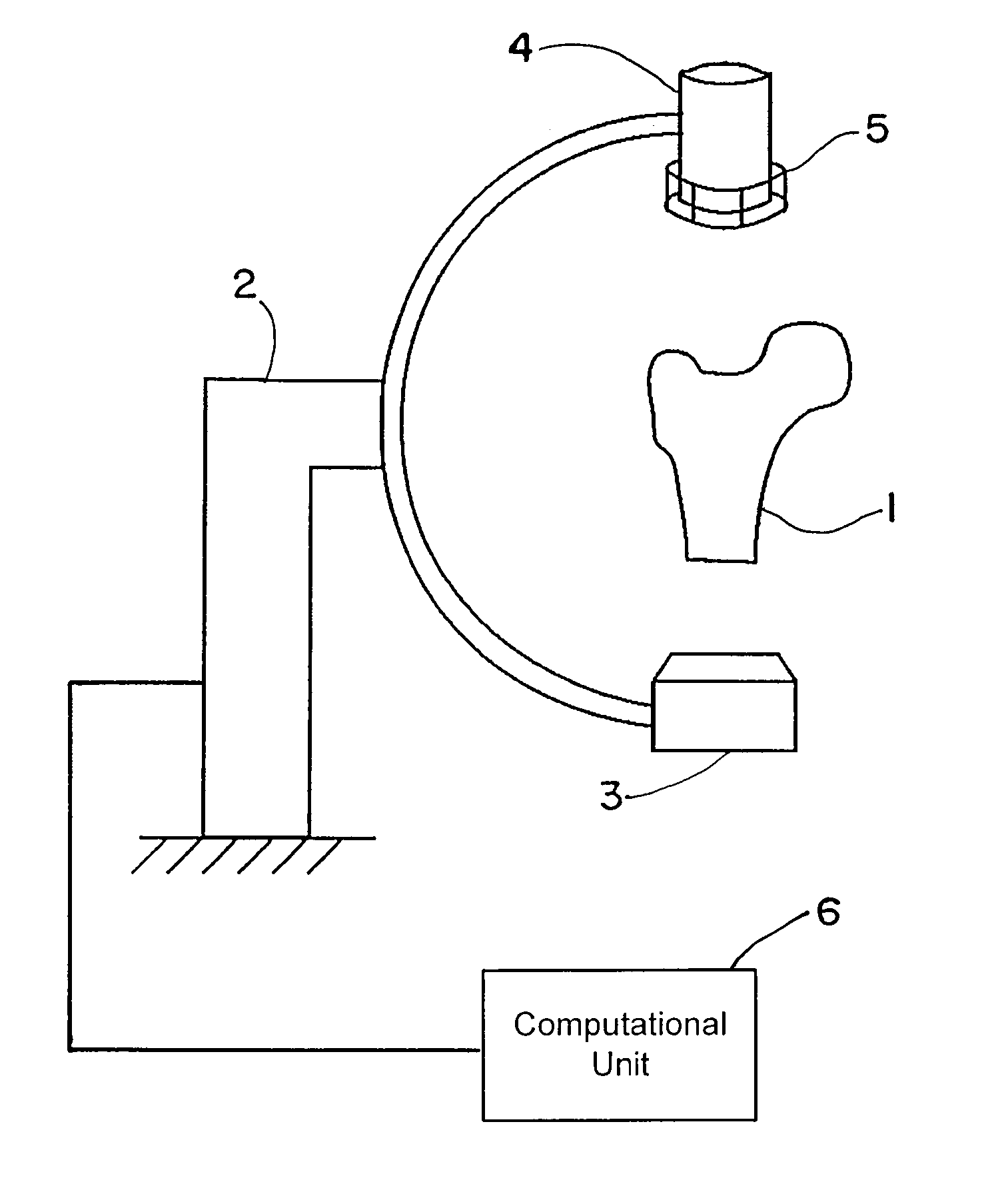
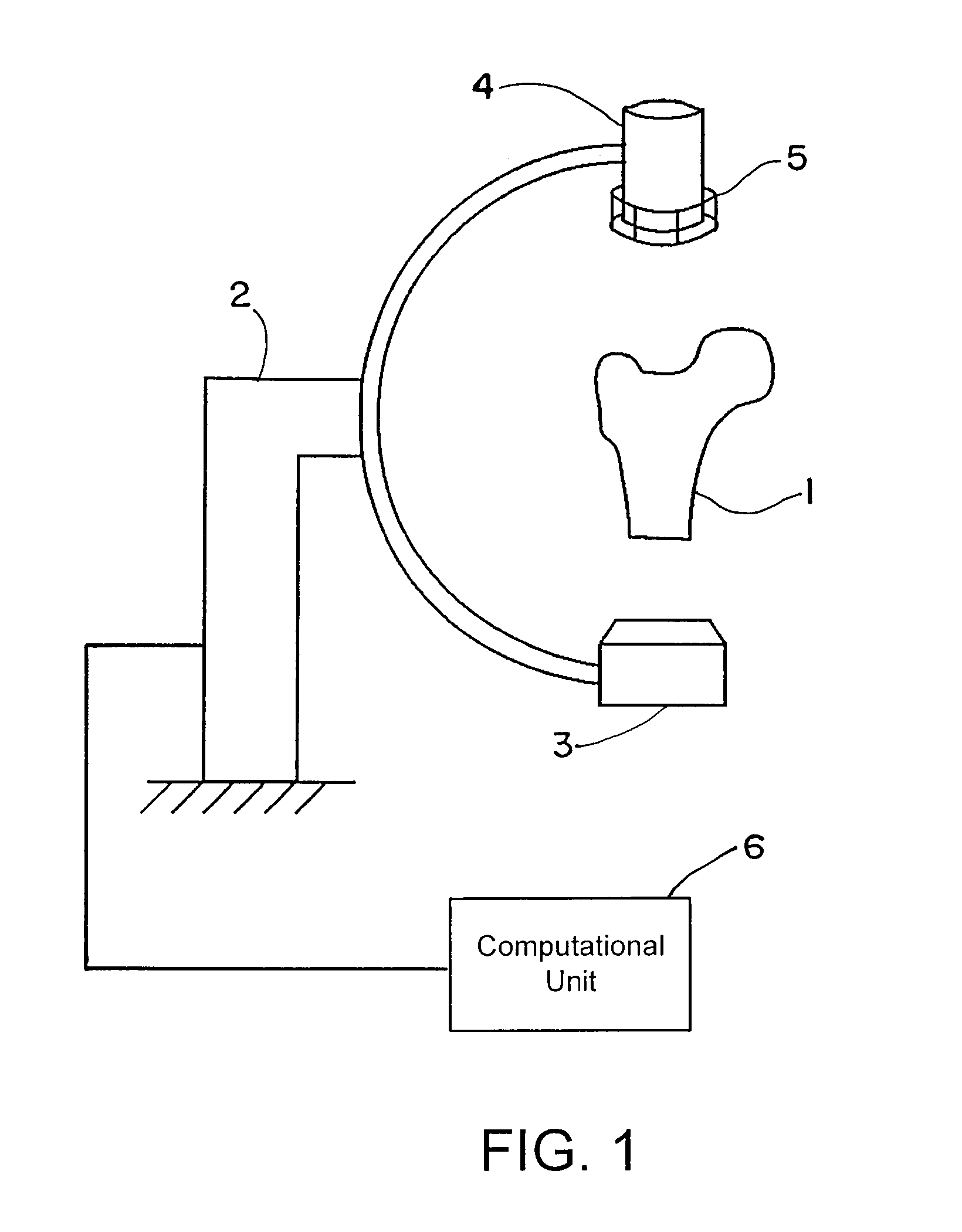
[0058]FIG. 1 shows an exemplary C-arc apparatus that can be used to obtain patient-specific X-ray images. An anatomic structure of interest, e.g., the proximal femur 1 of the patient, can be placed in the imaging unit 2. This imaging unit 2 may include a radiation source 3 and a detection device 4. A calibration device 5 connected to the detection device 4 can be used to determine the imaging parameters. The calibration device 5 may be placed anywhere between the radiation source 3 and the detection device 4, and attachment to the detection device is merely exemplary. Operatively coupled to the C-arc apparatus is a computational unit 6 that executes the algorithm described herein.

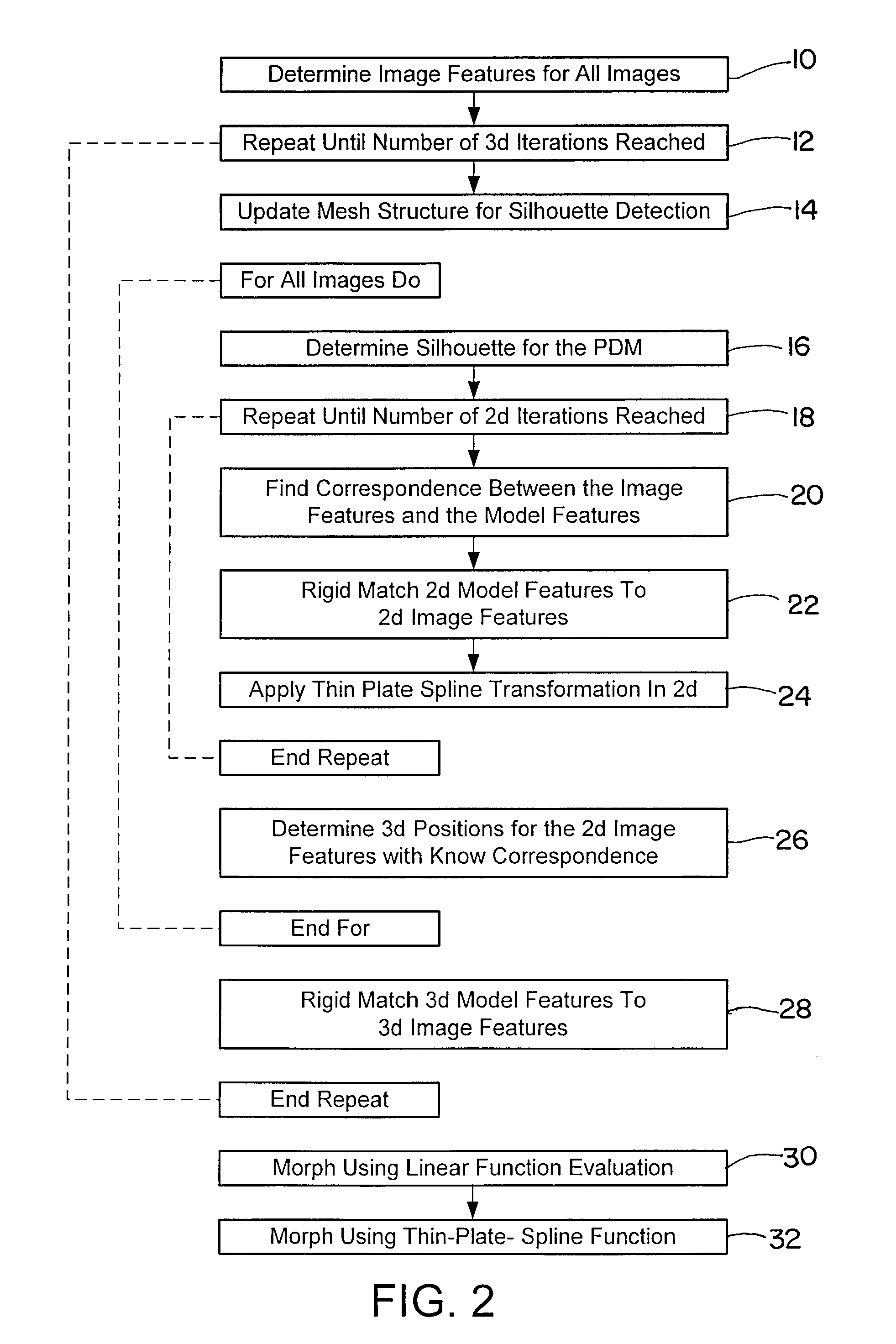
[0059] The image(s) obtained from the imaging device 2 can be used as input for the algorithm of FIG. 2 and executed by the computational unit 6. Beginning at block 10, image figures such as the shape, contour, outline or edge or gradients may be determined for all obtained two-dimensional images. At block...


PUM


Abstract

A method for generating a three-dimensional model of a structure based on at least one two-dimensional image of the structure includes obtaining a general three-dimensional model of the structure; determining at least one image feature from the at least one two-dimensional image; determining an orientation of the general three-dimensional model of the structure relative to the at least one two-dimensional image of the structure so that at least one image feature of a two-dimensional projection of the three-dimensional model match or at least approximate the at least one two-dimensional image feature; and after determining the orientation of the general three-dimensional model, morphing a form or shape of the general three-dimensional model to fit the at least one two-dimensional image.

Description

RELATED APPLICATION DATA [0001] This application claims priority of U.S. Provisional Application No. 60 / 826,786 filed on Sep. 25, 2006, which is incorporated herein by reference in its entirety.FIELD OF THE INVENTION [0002] The present invention relates generally to medical imaging, and more particularly to a method and apparatus for generating a three-dimensional (3D) model based on at least one two-dimensional (2D) image, such as the construction of a patient-specific three-dimensional model of a bone surface from one or more two-dimensional calibrated fluoroscopic images. BACKGROUND OF THE INVENTION [0003] Computer-assisted stereotactic systems that work with the aid of body structure data obtained from tomographic detection systems and with the assistance of X-ray images produced in situ are known, for example, from U.S. Pat. No. 4,791,934 and U.S. Pat. No. 5,799,055. Furthermore, x-ray imaging used to assist in operations is discussed in U.S. Pat. Nos. 5,967,982; 5,772,594; and...

Claims


Application Information

Patent Timeline
Patent Type & Authority Applications(United States)
IPC IPC(8): G06T17/00
CPCG06T7/0051G06T7/50
Inventor FEILKAS, THOMASZHENG, GUOYAN
Owner BRAINLAB
Why Eureka
Try Eureka