Magneto-resistive effect device, thin-film magnetic head, head gimbal assembly, and hard disk system

a magnetic head and magnetic head technology, applied in the direction of magnetic bodies, instruments, record information storage, etc., can solve the problems of 4%, less than satisfactory figure, and the possibility of inconvenien

Active Publication Date: 2008-01-24
TDK CORPARATION
View PDF6 Cites 16 Cited by
  • Summary
  • Abstract
  • Description
  • Claims
  • Application Information

AI Technical Summary

Benefits of technology

[0014]According to the invention, such an object is accomplished by the provision of a magneto-resistive effect device having a CPP (current perpendicular to plane) structure comprising a nonmagnetic spacer layer, and a fixed magnetized layer and a free layer stacked one upon another with said nonmagnetic spacer layer sandwiched between them, with a sense current applied in a stacking direction, wherein said free layer functions such that its magnetization direction changes depending on an external magnetic field, and said fixed magnetization layer is made up of a multilayer structure including a Heusler alloy layer, wherein Fe layers are formed on both plane sides of said Heusler alloy layer in the stacking direction with said Heusler alloy layer sandwiched between them.

Problems solved by technology

Referring to such GMR devices of the CPP structure, even when they have a multilayer structure capable of achieving practical reproduction gap lengths, the magneto-resistivity change ratio (MR ratio)—the ratio of a magneto-resistivity change with respect to resistance—is barely about 4%, a figure still practically less than satisfactory.
However, it has now been found through inventors' experimentation that when the Heusler alloy layer is formed in tight contact with the CoFe alloy layer, Co atoms contained in the CoFe alloy diffuse into the Heusler alloy, resulting in the likelihood of bringing about inconvenience such as a decrease in the spin polarizability of the Heusler alloy.

Method used


Image

  • Magneto-resistive effect device, thin-film magnetic head, head gimbal assembly, and hard disk system
  • Magneto-resistive effect device, thin-film magnetic head, head gimbal assembly, and hard disk system
  • Magneto-resistive effect device, thin-film magnetic head, head gimbal assembly, and hard disk system

Examples


first embodiment

Magneto-Resistive Effect Device Having a CPP Structure

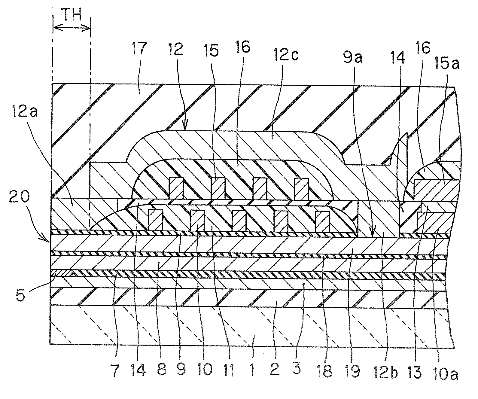
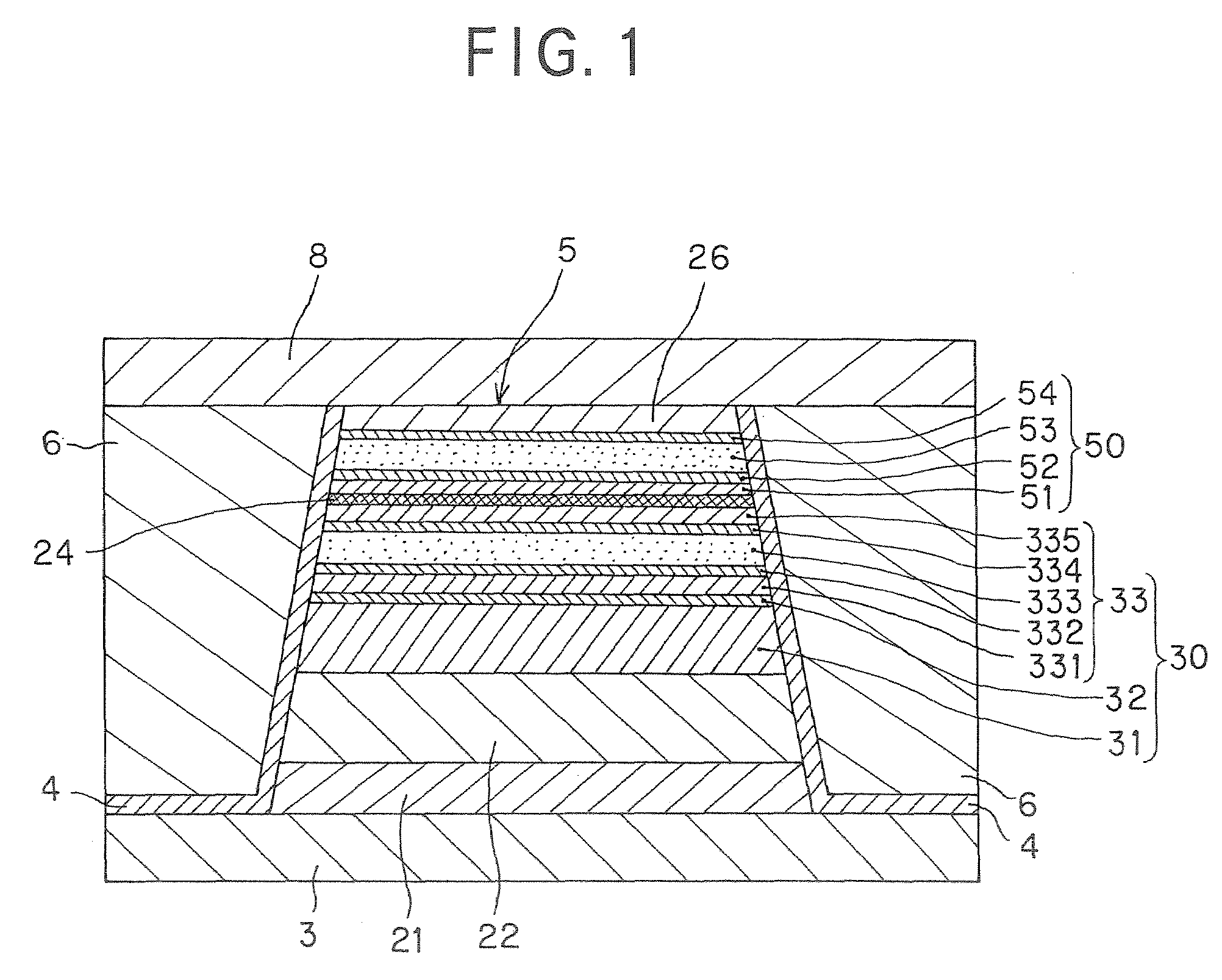
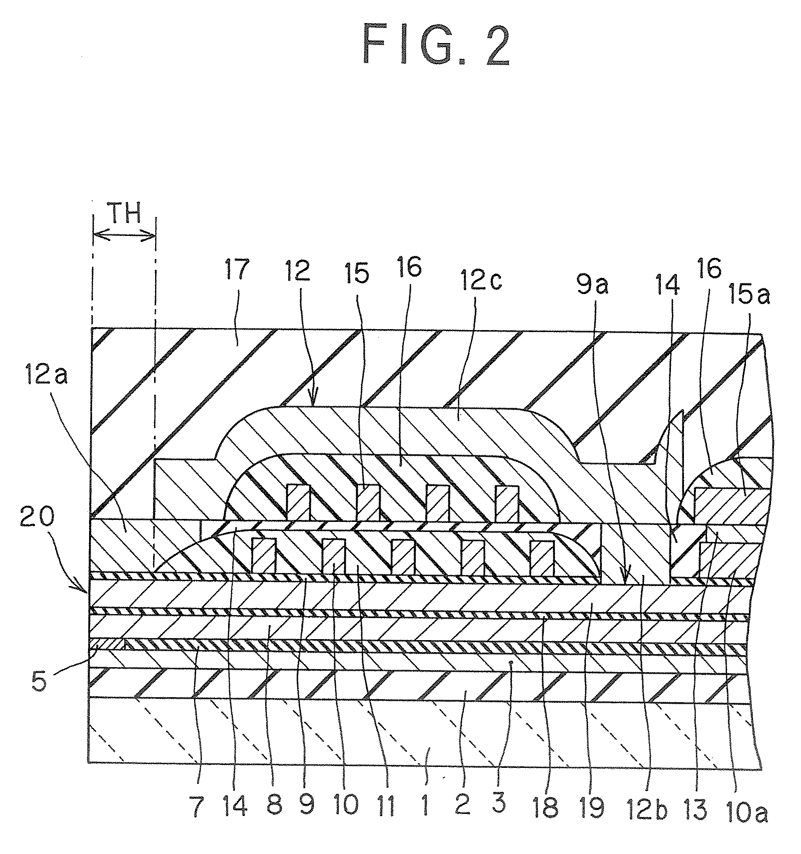
[0044]The construction of a reproducing head comprising the inventive magneto-resistive effect device of the CPP structure is now explained in details with reference to FIG. 1.

[0045]As noted above, FIG. 1 is a sectional view corresponding to a section of the reproducing head parallel with the medium opposite plane.

[0046]As shown in FIG. 1, the reproducing head according to the embodiment here comprises a first shield layer 3 and a second shield layer 8 that are located at a given space and opposed to each other, a magneto-resistive effect device 5 (hereinafter referred simply to as the MR device 5) interleaved between the first shield layer 3 and the second shield layer 8, an insulating film 4 adapted to cover two sides of the MR device 5 and a part of the upper surface of the first shield layer 3 along these sides, and two bias magnetic field-applying layers 6 adjacent to the two sides of the MR device 5 via the insulating layer...

second embodiment

Magneto-Resistive Effect Device of the CPP Structure

[0085]The magneto-resistive effective device of the CPP structure according to the second embodiment of the invention is now explained with reference to FIG. 4. The magneto-resistive effect device of the CPP structure according to the second embodiment shown in FIG. 4 differs from the aforesaid first embodiment in that a Heusler alloy layer 53 is applied to a free layer 50 alone. And of course, the Heusler alloy layer 53 is sandwiched between Fe layers 52 and 54.

[0086]More specifically, the magneto-resistive effect device of the CPP structure according to the second embodiment shown in FIG. 4 takes on a form that comprises, in order from the side of an underlay layer 21, an anti-ferromagnetic layer 22, an outer layer 31, a nonmagnetic intermediate layer 32, an inner layer 33, a nonmagnetic spacer layer 24, and a free layer 50 (a multilayer structure comprising underlay magnetic layer 51, Fe layer 52, Heusler alloy layer 53 and Fe l...

third embodiment

Magneto-Resistive Effect Device of the CPP Structure

[0089]The magneto-resistive effective device of the CPP structure according to the third embodiment of the invention is now explained with reference to FIG. 5. The magneto-resistive effect device of the CPP structure according to the second embodiment shown in FIG. 5 differs from the aforesaid first embodiment in that a Heusler alloy layer 333 is applied to a fixed magnetization layer 30 alone. And of course, the Heusler alloy layer 333 is sandwiched between Fe layers 332 and 334.

[0090]More specifically, the magneto-resistive effect device of the CPP structure according to the third embodiment shown in FIG. 5 takes on a form that comprises, in order from the side of an underlay layer 21, an anti-ferromagnetic layer 22, an outer layer 31, a nonmagnetic intermediate layer 32, an inner layer 33 (a multilayer structure comprising underlay magnetic layer 331, Fe layer 332, Heusler alloy layer 333, Fe layer 334 and intermediate magnetic ...


PUM

PropertyMeasurementUnit
thicknessaaaaaaaaaa
thicknessaaaaaaaaaa
thicknessaaaaaaaaaa

Abstract

The invention provides a magneto-resistive effect device having a CPP (current perpendicular to plane) structure comprising a nonmagnetic spacer layer, and a fixed magnetized layer and a free layer stacked one upon another with said nonmagnetic spacer layer sandwiched between them, with a sense current applied in a stacking direction, wherein said free layer functions such that its magnetization direction changes depending on an external magnetic field, and is made up of a multilayer structure including a Heusler alloy layer, wherein an Fe layer is formed on one of both planes of said Heusler alloy layer in the stacking direction, wherein said one plane is near to at least a nonmagnetic spacer layer side, and said fixed magnetization layer is made up of a multilayer structure including a Heusler alloy layer, wherein Fe layers are formed on both plane sides of said Heusler alloy layer in the stacking direction with said Heusler alloy layer sandwiched between them. It is thus possible to prevent diffusion of Co atoms contained in the CoFe layer into the Heusler alloy layer, enabling the decrease in the spin polarizability of the Heusler alloy layer to be hold back and achieving a high MR ratio.

Description

BACKGROUND OF THE INVENTION[0001]1. Field of the Invention[0002]The present invention relates to a magneto-resistive effect device for reading the magnetic field strength of a magnetic recording medium or the like as signals and a thin-film magnetic head comprising that magneto-resistive effect device as well as a head gimbal assembly and a magnetic disk system comprising that thin-film magnetic head.[0003]2. Explanation of the Prior Art[0004]With recent improvements in the plane recording density of hard disk systems, there has been growing demands for improvements in the performance of thin-film magnetic heads. For the thin-film magnetic head, a composite type thin-film magnetic head has been widely used, which has a structure wherein a reproducing head having a read-only magneto-resistive effect device (hereinafter often referred to as the MR (magneto-resistive) device for short) and a recording head having a write-only induction type magnetic device are stacked on a substrate.[0...

Claims


Application Information

Patent Timeline
Patent Type & Authority Applications(United States)
IPC IPC(8): G11B5/33
CPCB82Y25/00G01R33/093G11B5/3906H01F10/3295H01F10/1936H01F10/3272H01L43/10G11B5/3967H10N50/85
Inventor MIZUNO, TOMOHITOTSUCHIYA, YOSHIHIROSHIMAZAWA, KOJI
Owner TDK CORPARATION
Why Eureka
Try Eureka