Burner Device with a Porous Body

a burner and body technology, applied in the direction of fuel cells, combustion process, plant protection, etc., can solve the problems of high exhaust emissions, ruined burners, or even burners, or parts thereof, and achieve the effect of efficient utilization of heat resulting from combustion

Inactive Publication Date: 2008-01-24
WEBASTO AG
View PDF23 Cites 11 Cited by
  • Summary
  • Abstract
  • Description
  • Claims
  • Application Information

AI Technical Summary

Benefits of technology

[0021] To efficiently exploit the heat resulting from combustion, it is preferably provided hat the combustion chamber is in thermal contact with a heat exchanger element.

Problems solved by technology

However, the small pore zone of the porous body results in a considerable pressure loss,.
This is why, despite the flame trap, flashback may occur especially in the istationary operating points of the burner which results in higher exhaust emissions or even the burner, or parts thereof, being ruined as a result.

Method used


Image

  • Burner Device with a Porous Body
  • Burner Device with a Porous Body

Examples


Embodiment Construction

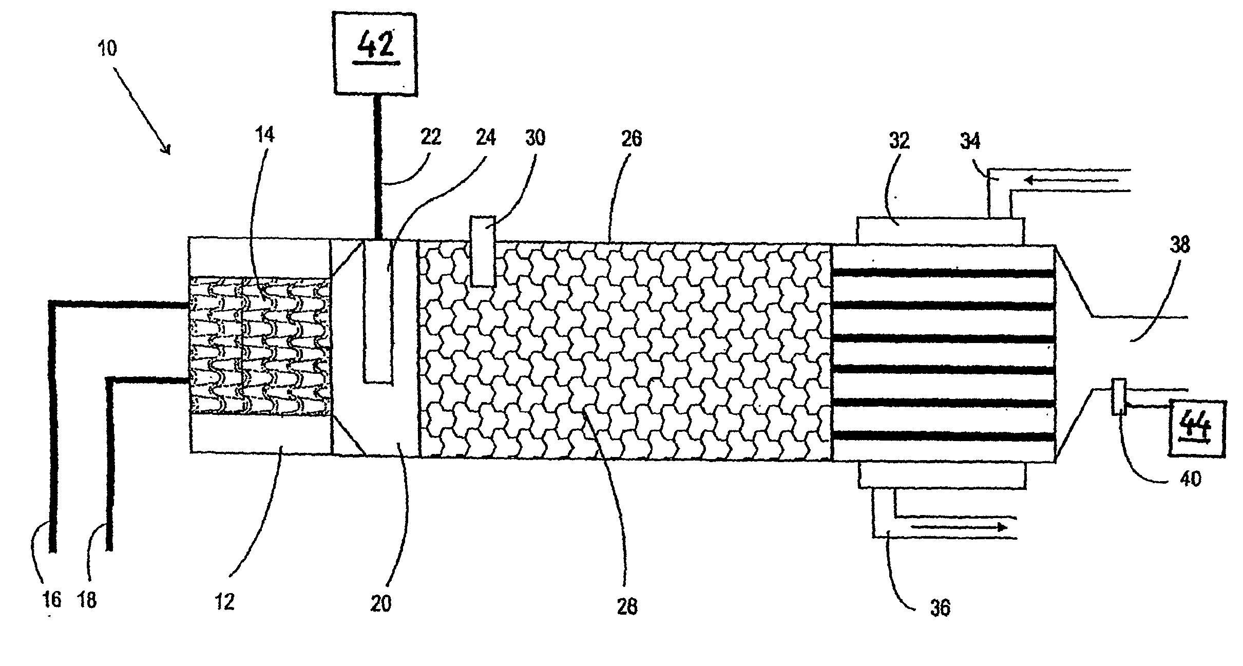
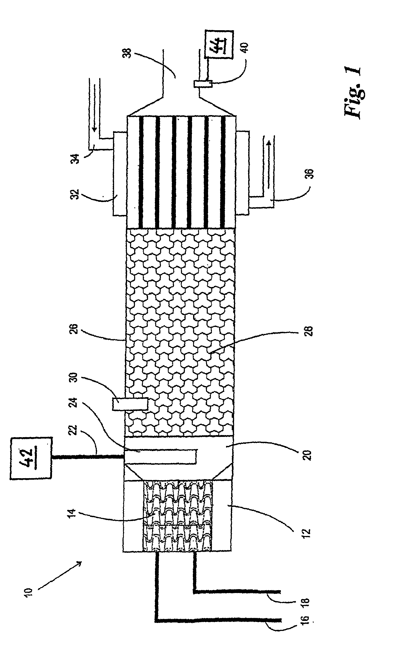
[0024] Referring now to FIG. 1, there is illustrated a fuel cell stack comprising a fuel cell module 42 to which a burner device 10 in accordance with the invention is assigned as an afterburner. Liquid fuel and combustion air are fed via a fuel inlet line 16 and a combustion air inlet line 18, respectively, into the burner device 10 which is, preferably, configured as a metallic evaporator element 14, particularly as metallic foam. Over the surface area of the evaporator element 14, which may be catalytically coated, the supply of liquid fuel evaporates and is mixed with the combustion air.

[0025] From the evaporation zone, the resulting combustion mixture flows into a mixture zone 20 into which fuel gas is introduced via a fuel gas inlet line 22 which, in this case, is the anode exhaust of the fuel cell module 42. In the mixture zone 20, the fuel gas inlet line 22 preferably has the form of a perforated tube or of a porous body, particularly, a porous ceramic body. This end portio...


PUM

PropertyMeasurementUnit
metallicaaaaaaaaaa
electrical energyaaaaaaaaaa
surface areaaaaaaaaaaa

Abstract

A burner device having a burner chamber (26) filled at least partially by a porous body (28), an evaporation zone (12) upstream of the burner chamber (26) for evaporating liquid fuel supplied via a fuel inlet line (16), an igniter (30) for igniting a combustion mixture of evaporated liquid fuel and combustion air supplied via a combustion air inlet line (18) to the evaporation zone (12) as well as an exhaust discharge (38) downstream of the combustion chamber (26). A mixing zone (20) is disposed between the evaporation zone (14) and the combustion chamber (26) in which fuel gas is introduced via a fuel gas inlet line (22, 24) and is mixed with the combustion air and/or the combustion mixture. The burner device can be used as an afterburner in a fuel cell stack.

Description

BACKGROUND OF THE INVENTION [0001] 1. Field of the Invention [0002] The invention relates to a burner device comprising a burner chamber filled at least partially by a porous body, an evaporation zone upstream of the burner chamber for evaporating liquid fuel supplied via a fuel inlet line, an igniter for igniting a combustion mixture of evaporated liquid fuel and combustion air supplied via a combustion air inlet line to the evaporation zone as well as an exhaust discharge downstream of the combustion chamber. [0003] 2. Description of Related Art [0004] One such burner device, also termed a porous burner, is known from German Patent Application DE 101 60 837 A1. Typical of a porous burner is its porous body, i.e., a body of porous material which at least partially fills the burner chamber. The porous material of such a porous body is especially a non-oxidizing material, such as SiC, SiN, or also high-temperature oxides, such as, for example, Al2O3 or ZrO2. Porous bodies are often e...

Claims


Application Information

Patent Timeline
Patent Type & Authority Applications(United States)
IPC IPC(8): F23D11/36F23C99/00F23D14/16F23G7/06H01M8/06
CPCF23C99/006F23D2204/10F23G7/065F23G2202/50Y02E60/50H01M8/04022H01M8/0662Y02E20/12F23N2037/30F23N2237/30F23C99/00H01M8/04H01M8/06
Inventor KAEDING, STEFANLAWRENCE, JEREMY
Owner WEBASTO AG
Why Eureka
Try Eureka