Iontophoresis device

US20080021372A1Inactive Publication Date: 2008-01-24ERCHONIA CORP

Image

  • Iontophoresis device
  • Iontophoresis device
  • Iontophoresis device

Examples


Embodiment Construction

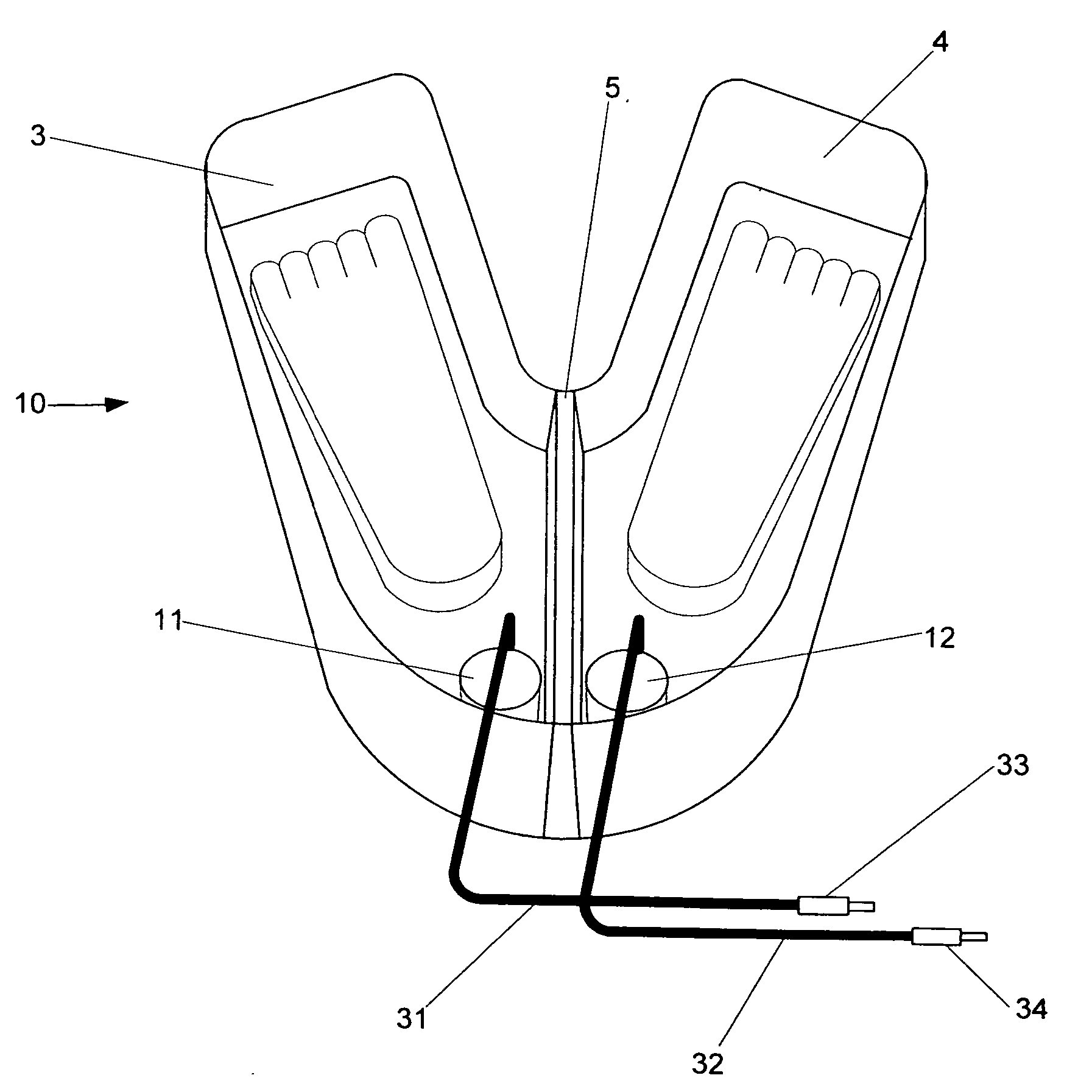
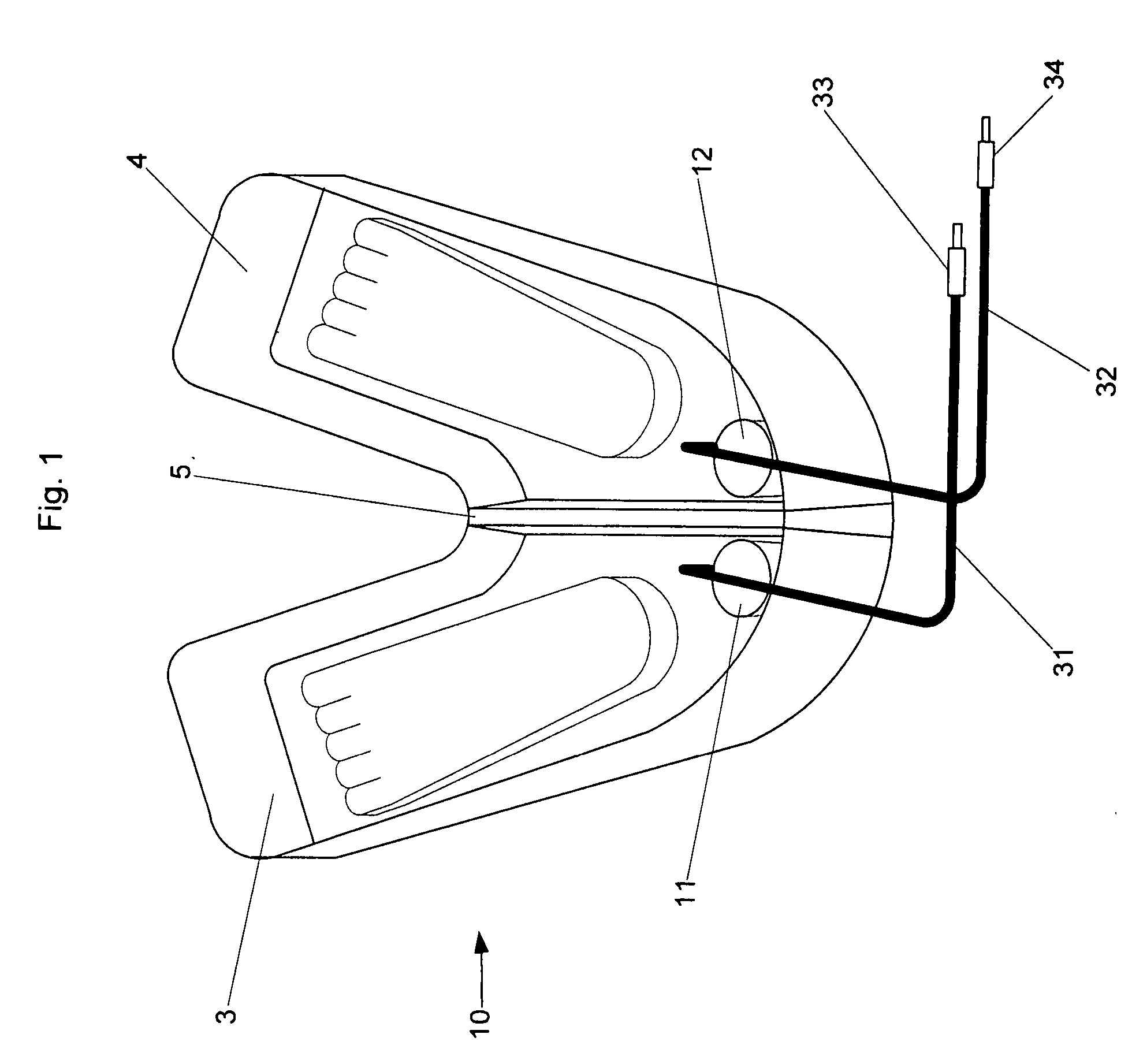
[0018] Referring to FIGS. 1-7, there is illustrated the preferred embodiment of the present invention, designated generally as device 10, which is used to perform iontophoresis. FIG. 1 illustrates device 10. Device 10 has a first reservoir 3 and a second reservoir 4 such that the liquid in reservoir 3 does not contact the liquid in reservoir 4. The reservoirs may be separate vessels or a single vessel separated by a partition 5. Also located in reservoir 3 and reservoir 4 are first and second arrays 11 and 12, respectively.

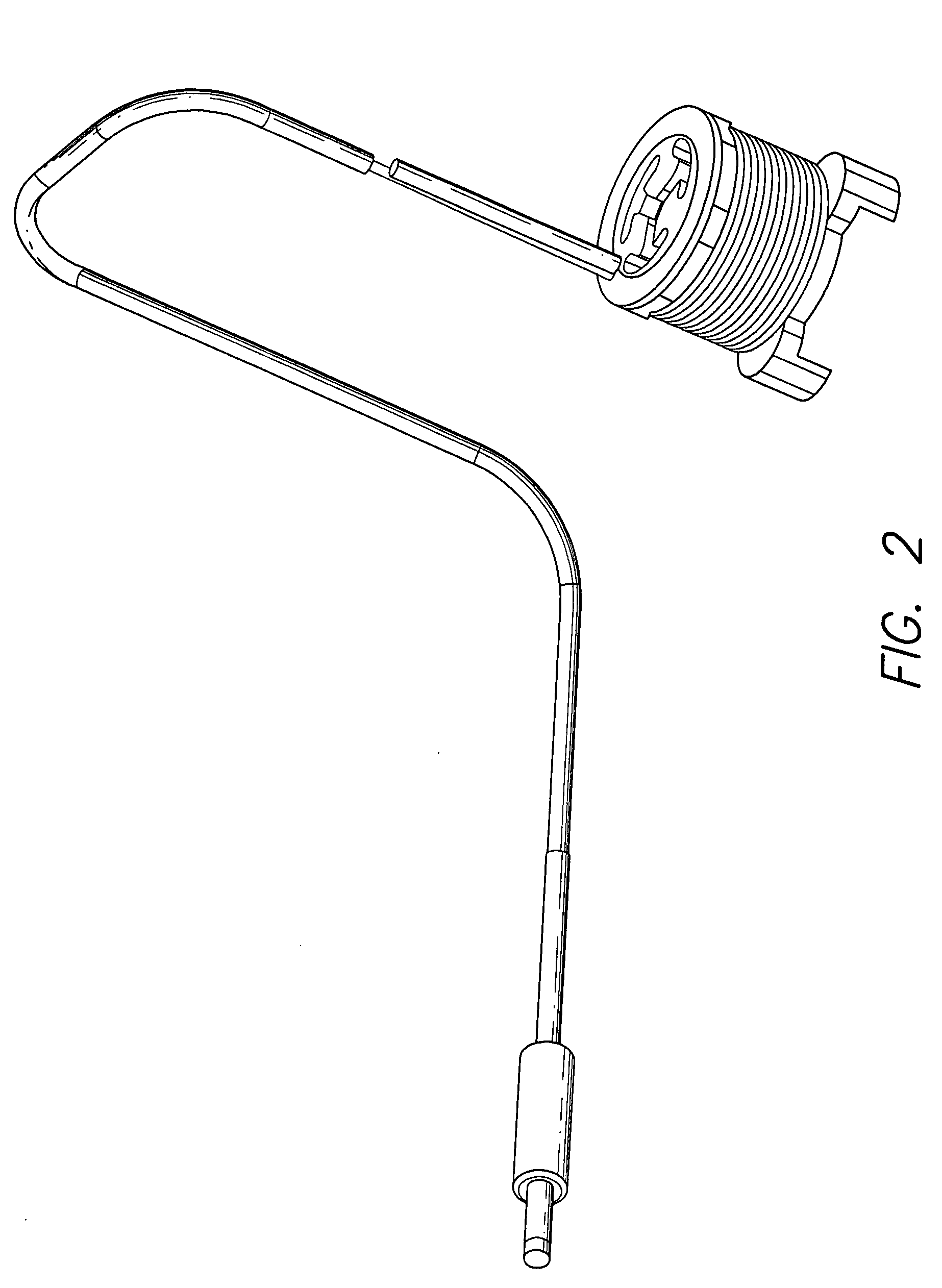
[0019]FIGS. 2, 3 and 4 illustrate first and second arrays 11 and 12, which are used to generate a current and drive ions contained in reservoirs 3 and 4 through the skin. Arrays 11 and 12 each have a cap 21 and a base 22 that form a housing to hold a first electrode 23 at a fixed distance from a second electrode. Cap 21 and base 22 have apertures in them through which the liquid can flow. The solution should be able to freely flow between the electrodes. Free hor...


PUM


Abstract

A device for iontophoresis. A first battery-powered array is submerged into a liquid contained in a first reservoir and a second battery-powered array is submerged into a liquid contained in a second reservoir. Each array has one or more degradable electrodes that releases ions into the liquid in the reservoir. The electrodes can be copper, zinc, steel, nickel, or a combination thereof. At the first array one of the electrodes can be positively charged while at the second array one of the electrodes can be negatively charged. Alternatively, an electrode at the second array can be positively charged while an electrode at the first array is negatively charged. The solution in the reservoir may also contain positively or negatively charged ions. Powering the arrays causes the charged molecules contained in the liquid to transport through a patient's skin. The device uses a current and voltage regulator to deliver a regulated amount of current through the arrays regardless of the conductivity of the liquid, and electronic circuitry is used to control the duration, polarity, electrode choice, and intensity of the treatment. Excessive heat is dissipated with a heat sink.

Description

CROSS-REFERENCE TO RELATED APPLICATIONS [0001] This application is a continuation in part of co-pending U.S. application Ser. No. 10 / 346149 filed Jan. 15, 2003.FIELD OF INVENTION [0002] This invention relates generally to iontophoresis and particularly to a device for non-invasively conducting a charged substance, such as a medication or bioactive-agent, transdermally. BACKGROUND [0003] Iontophoresis is a needle-free, non-invasive technology for delivering nutrients, medicines, vitamins, minerals, therapeutic agents, drugs or other bioactive agents through the skin using a small electric current. These beneficial bioactive agents are referred to herein generally as medicaments. In general, delivering such medicaments through iontophoresis involves applying an electromotive force that transports ions through the stratum corneum, the outermost layer of skin, and into the dermis, the inner layer of skin that is comprised of connective tissue, blood and lymph vessels, sweat glands, hair...

Claims


Application Information

Patent Timeline
24 Jan 2008
Publication
US20080021372A1
IPC
A61N1/30; A61H35/00; A61N1/44
CPC
A61N1/445; A61H35/006
Inventors
SHANKS, STEVEN C.; TUCEK, KEVIN B.