
Method and Apparatus for Body Fluid Sampling and Analyte Sensing

a body fluid and analyte technology, applied in the field of body fluid sampling and analyte sensing, can solve the problem of insufficient feedback control, and achieve the effects of optimizing cutting tissue, improving cutting efficiency, and increasing the depth accuracy of the penetrant member

Active Publication Date: 2008-01-24
SANOFI AVENTIS DEUT GMBH
View PDF60 Cites 151 Cited by
  • Summary
  • Abstract
  • Description
  • Claims
  • Application Information

AI Technical Summary

Benefits of technology

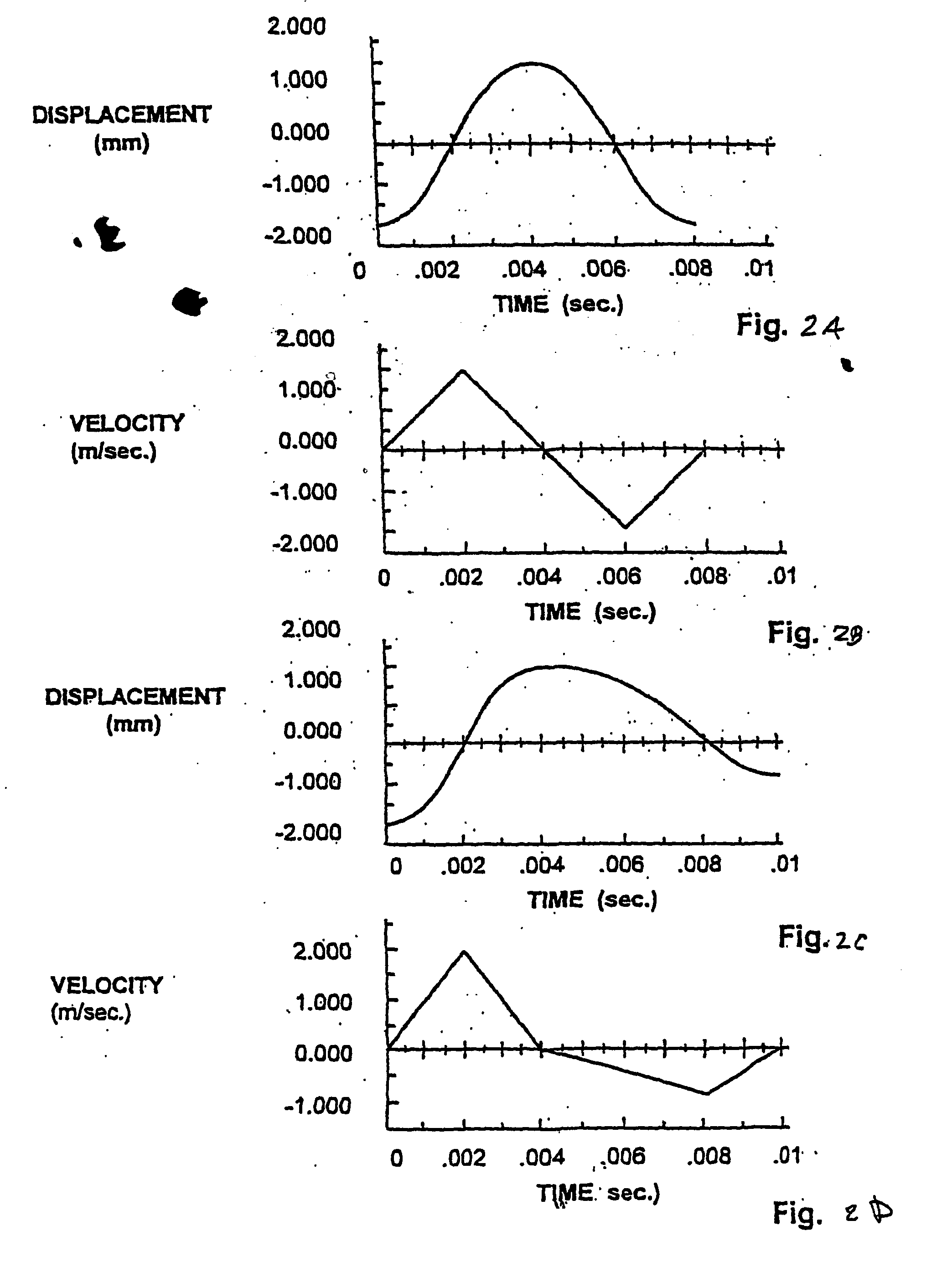
[0008]In one aspect, the present invention provides improved lancing devices operating with adaptive control algorithms. Because of the very high speeds that embodiments of the present invention may move their penetrating members, feedback control may not be sufficient, due to the short amount of time available. In one embodiment, the present invention provides desired parameters, based on the models of the penetrating member, the penetrating member driver, and the targeted tissue. Based on this model, the system may have predictive information stored in lookup tables on how to drive the penetrating member driver and when to apply braking force so that the device performs as desired to arrive at a desired depth and to provide a desired level of cutting efficiency and / or performance.
[0010]In another embodiment, the present invention relates to the way that an electronically driven lancing device controls the trajectory of the inbound lancet up to the point of maximum extension or penetration into a target tissue. This is the point of maximum penetration of the lancet into the skin. This embodiment of the present invention comprises a control algorithm, that when combined with the necessary hardware to execute the control instructions, increases the depth accuracy of the penetrating member. The present invention also provides improved cutting efficiency by providing lancet behavior that is optimized for cutting tissue.

Problems solved by technology

Because of the very high speeds that embodiments of the present invention may move their penetrating members, feedback control may not be sufficient, due to the short amount of time available.

Method used


Image

  • Method and Apparatus for Body Fluid Sampling and Analyte Sensing
  • Method and Apparatus for Body Fluid Sampling and Analyte Sensing
  • Method and Apparatus for Body Fluid Sampling and Analyte Sensing

Examples


Embodiment Construction

[0072]The present invention provides a multiple analyte detecting member solution for body fluid sampling. Specifically, some embodiments of the present invention provides a multiple analyte detecting member and multiple penetrating member solution to measuring analyte levels in the body. The invention may use a high density design. It may use penetrating members of smaller size, such as but not limited to diameter or length, than known lancets. The device may be used for multiple lancing events without having to remove a disposable from the device. The invention may provide improved sensing capabilities. At least some of these and other objectives described herein will be met by embodiments of the present invention.

[0073]It is to be understood that both the foregoing general description and the following detailed description are exemplary and explanatory only and are not restrictive of the invention, as claimed. It must be noted that, as used in the specification and the appended c...


PUM


Abstract

A method of controlling a penetrating member is provided. The method comprises providing a lancing device comprising a penetrating member driver having a position sensor and a processor that can determine the relative position and velocity of the penetrating member based on measuring relative position of the penetrating member with respect to time; providing a predetermined velocity control trajectory based on a model of the driver and a model of tissue to be contacted. In some embodiments, a feedforward control to maintain penetrating member velocity along said trajectory.

Description

BACKGROUND OF THE INVENTION[0001]Lancing devices are known in the medical health-care products industry for piercing the skin to produce blood for analysis. Typically, a drop of blood for this type of analysis is obtained by making a small incision in the fingertip, creating a small wound, which generates a small blood droplet on the surface of the skin.[0002]Early methods of lancing included piercing or slicing the skin with a needle or razor. Current methods utilize lancing devices that contain a multitude of spring, cam and mass actuators to drive the lancet. These include cantilever springs, diaphragms, coil springs, as well as gravity plumbs used to drive the lancet. The device may be held against the skin and mechanically triggered to ballistically launch the lancet. Unfortunately, the pain associated with each lancing event using known technology discourages patients from testing. In addition to vibratory stimulation of the skin as the driver impacts the end of a launcher sto...

Claims


Application Information

Patent Timeline
IPC IPC(8): A61B5/151A61BA61B5/15
CPCA61B5/1411A61B5/150022A61B5/150152A61B5/150167A61B5/150175A61B5/150412A61B5/150755A61B5/15113A61B5/15123A61B5/15151A61B5/15161A61B5/157
Inventor BRIGGS, BARRY DEANMARSOT, TRAVISHEGENER, JASONFREEMAN, DOMINIQUE M.BOECKER, DIRKALDEN, DONSCHUMANN, MATTBEADMAN, MIKE
Owner SANOFI AVENTIS DEUT GMBH
Learn More