Linear electric motor controller and system for providing linear control

a technology of linear control and electric motor, which is applied in the direction of automatic controllers, logic circuits, dynamo-electric machines, etc., can solve the problems of introducing a choppy control quality, relatively inaccurate control of electric motors, and choppy or stepwise levels of control, so as to reduce vehicle size, increase fuel economy, and reduce weigh

Inactive Publication Date: 2008-01-31
2112376 ONTARIO
View PDF84 Cites 3 Cited by
  • Summary
  • Abstract
  • Description
  • Claims
  • Application Information

AI Technical Summary

Benefits of technology

[0011] The present invention now provides an electric motor controller that can be both smaller and lighter in weight than a switch-mode controller of the prior art. This can help increase fuel economy, decrease vehicle size, or increase the space available within the vehicle for other uses, as well as combinations thereof, all of which are highly desirable achievements. The invention also optionally, but preferably, packages the circuitry of the controller into an integrated circuit to further reduce the weight and size of the controller.
[0012] The controller includes an internal feedback mechanism to minimize control and monitoring latency, which provides for a more accurate control of the electric motor speed. This mechanism optionally, but preferably, incorporates a digital conversion to generate the motor voltage and current, thereby allowing for further increased accuracy compared to conventional low-pass filters.
[0013] The linear motor controller can also include a suitable heat sink, capable of conducting heat from the controller, wherein the heat sink is made of a material and designed so as to maximize the dissipation of heat from the controller. This enables the controller to be located in closer proximity to plastic components and / or a plastic housing, which also then allows for the controller module to be designed smaller if desired. The controller housing and plastic components are designed to be more capable of withstanding the increased wattage of heat dissipated by the controller, thereby also allowing for the controller to be placed in closer proximity to the plastic components and / or housing, thereby also contributing to reduction in size of the controller module. Additionally, the placement of the controller is preferably optimized within a cooling airflow so as to facilitate heat dissipation from the controller through the heat sink.
[0018] The controller can also be packaged inside a controller module for ease of assembly into a final product, such as an automobile. Thus, the invention also relates to an electronic controller module including an electronic controller that generates at least about 15 W of heat, an enclosure made of at least one heat-resistant material configured and dimensioned to substantially surround and physically protect the controller, at least one electrically-conductive member to provide input or output of at least one electrical signal through the enclosure to the controller, and a heat sink operatively associated with the controller to receive heat therefrom, the heat sink being configured and dimensioned to dissipate a sufficient amount of heat to inhibit or avoid damage to the controller and enclosure.
[0023] The invention also relates to a method for dissipating heat from an electronic controller by providing an enclosure around the electronic controller which generates at least about 15 W of heat during operation, associating a heat sink with the controller to receive heat therefrom, and dissipating a sufficient amount of heat to inhibit or avoid damage to the controller and enclosure. In one embodiment, the controller generates at least about 20 W to 150 W during operation. In another embodiment, at least about 90 percent of the heat generated is dissipated via the heat sink.

Problems solved by technology

A resistive divider operates by modulating the power provided to the electric motor by a constant or adjustable amount, resulting in a choppy or stepwise level of control.
PWM results in a relatively inaccurate control of an electric motor, and may also introduce a choppy quality of control.
The speed of the electric motor has a linear relationship with the voltage of the power supplied to the motor, hence the term “linear.” These systems are characterized by an undesirably large latency period, i.e., between detection and correction of the desired motor speed.
The widespread use of linear controllers for control of present-day variable speed electric motors, however, has been frustrated largely due to the large amount of heat generated by such controllers, and the difficulty thus encountered in practice when using such controllers.
Linear controllers used previously were designed so that the controller was remotely located from heat-sensitive structures, which tended to result in increased size of the controller module.
The difficulty in cooling such linear controllers, thermal melting and breakdown of the material enclosing linear controller units, and a need for placement of the controller within a cooling air stream has limited the use of such controllers in practical applications.

Method used


Image

  • Linear electric motor controller and system for providing linear control
  • Linear electric motor controller and system for providing linear control
  • Linear electric motor controller and system for providing linear control

Examples


Embodiment Construction

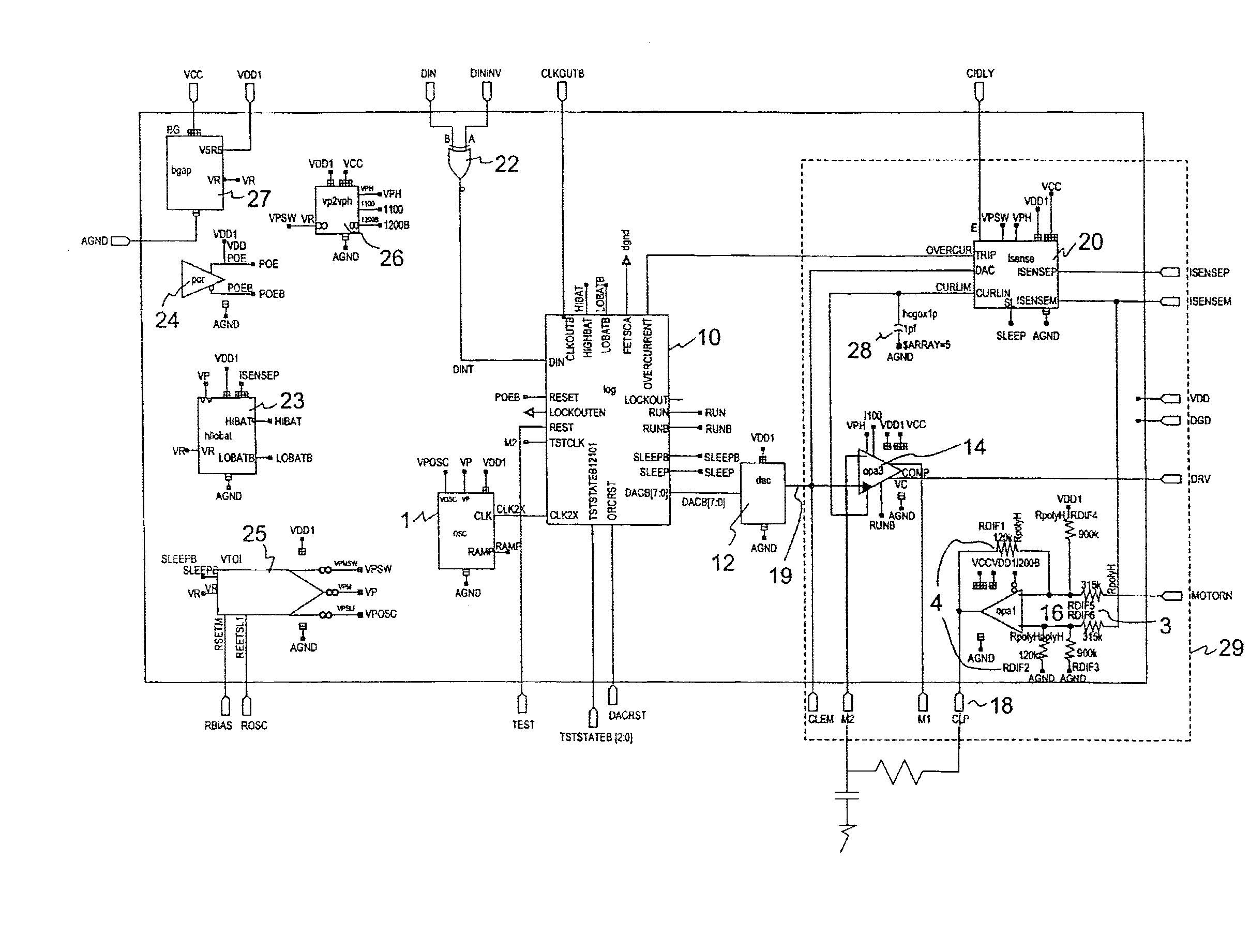
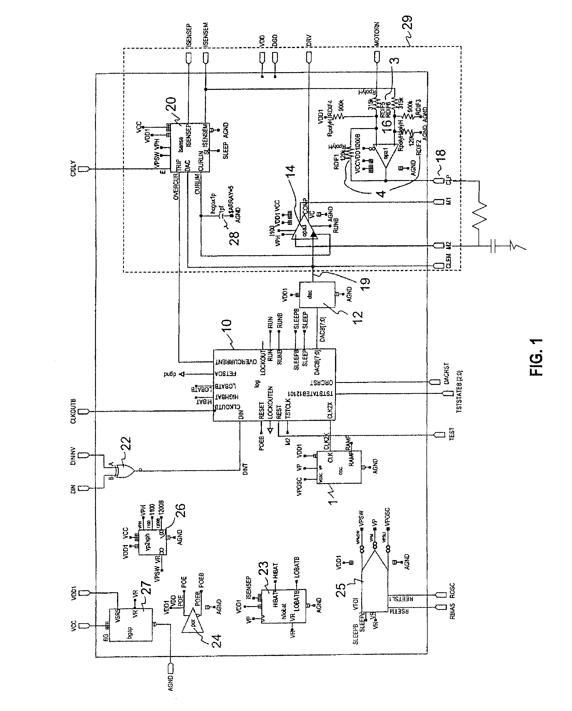
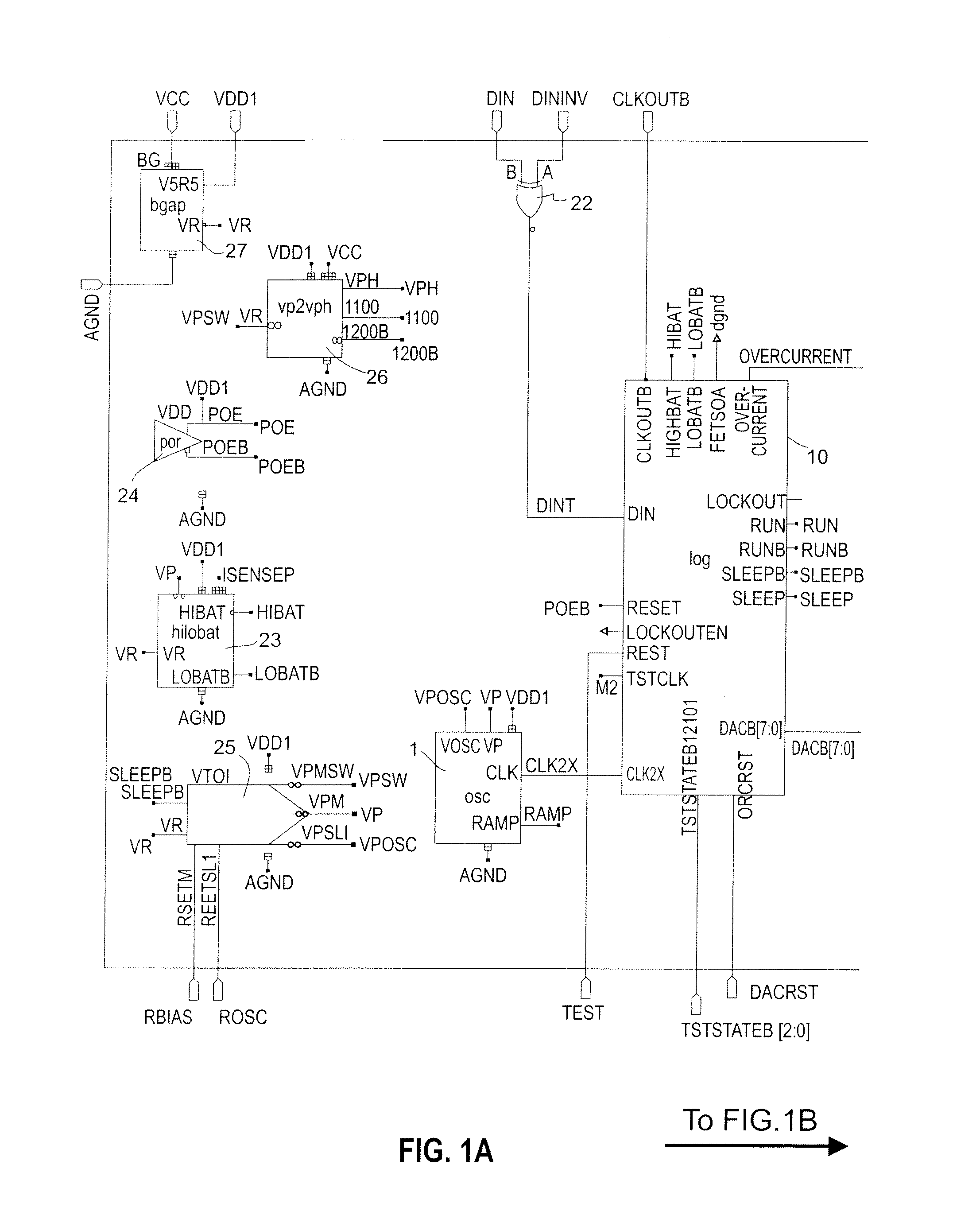
[0031] In accordance with a preferred embodiment of the invention, a method and system is provided to enable a linear electric motor controller that is smaller, lighter in weight, or both, compared to switch-mode controllers of the prior art. By packaging the linear controller of an embodiment of the current invention in an integrated circuit, additional weight and / or size savings can be realized. It has now been discovered that such linear controllers can be prepared by advantageously including an internal feedback mechanism to monitor the voltage and thus speed of the controlled motor, which can provide superior control compared to the switch mode, or PWM, type controller. The inclusion of at least one internal feedback mechanism facilitates a decreased latency between detection and correction of deviations of the controlled electric motor speed. This can advantageously minimize control latency to facilitate more accurate control of the electric motor speed.

[0032] In one embodime...


PUM


Abstract

The invention relates to a method of, and system for, linear speed control for an electric motor, in which a digital to analog converter means is used for converting an 8-bit digital signal to an analog voltage for setting voltage across a motor, a digital state machine means is used for converting the duty cycle of an input signal for output to the digital to analog converter means, and a closed loop feedback loop means is used for monitoring and setting the voltage across the motor. An over-current sense circuit can be used for monitoring the current across the electric motor. An over / under voltage sense circuit can be used for monitoring voltage of the electric motor. The resulting 8-bit digital control signal is converted to an analog voltage for the electric motor. Such methods and systems find particular use in automotive applications.

Description

CROSS-REFERENCE TO RELATED APPLICATIONS [0001] This application is a continuation application of co-pending U.S. patent application Ser. No. 10 / 017,232, filed Dec. 13, 2001, now allowed. The entire contents of the prior pending application is hereby incorporated herein by express reference thereto.FIELD OF THE INVENTION [0002] The invention relates to a method of, and system for, providing linear control of electric motors. Specifically, the present invention is directed to a method of and system for linear control of variable speed electric motors, such as for use in automotive vehicles. BACKGROUND OF THE INVENTION [0003] The electrical systems for which many electronic controllers are presently designed are typically, such as in automobiles, 12 V or 24 V systems. The controllers are typically attached to the car dashboard, seat bottom, or the like by being screwed into place. [0004] Control of present-day electric motors, such as those used in the heating ventilating and air condi...

Claims


Application Information

Patent Timeline
Patent Type & Authority Applications(United States)
IPC IPC(8): G05B19/045G05B11/00H02P7/00H02H7/08H02P29/02
CPCH02P29/02H02H7/0822
Inventor LACROIX, MICHAEL CHARLES
Owner 2112376 ONTARIO
Why Eureka
Try Eureka