Power storage device
- Summary
- Abstract
- Description
- Claims
- Application Information
AI Technical Summary
Benefits of technology
Problems solved by technology
Method used
Image
Examples
embodiment 1
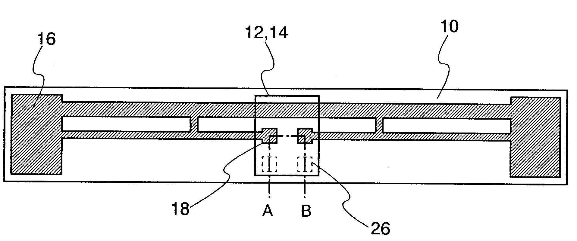
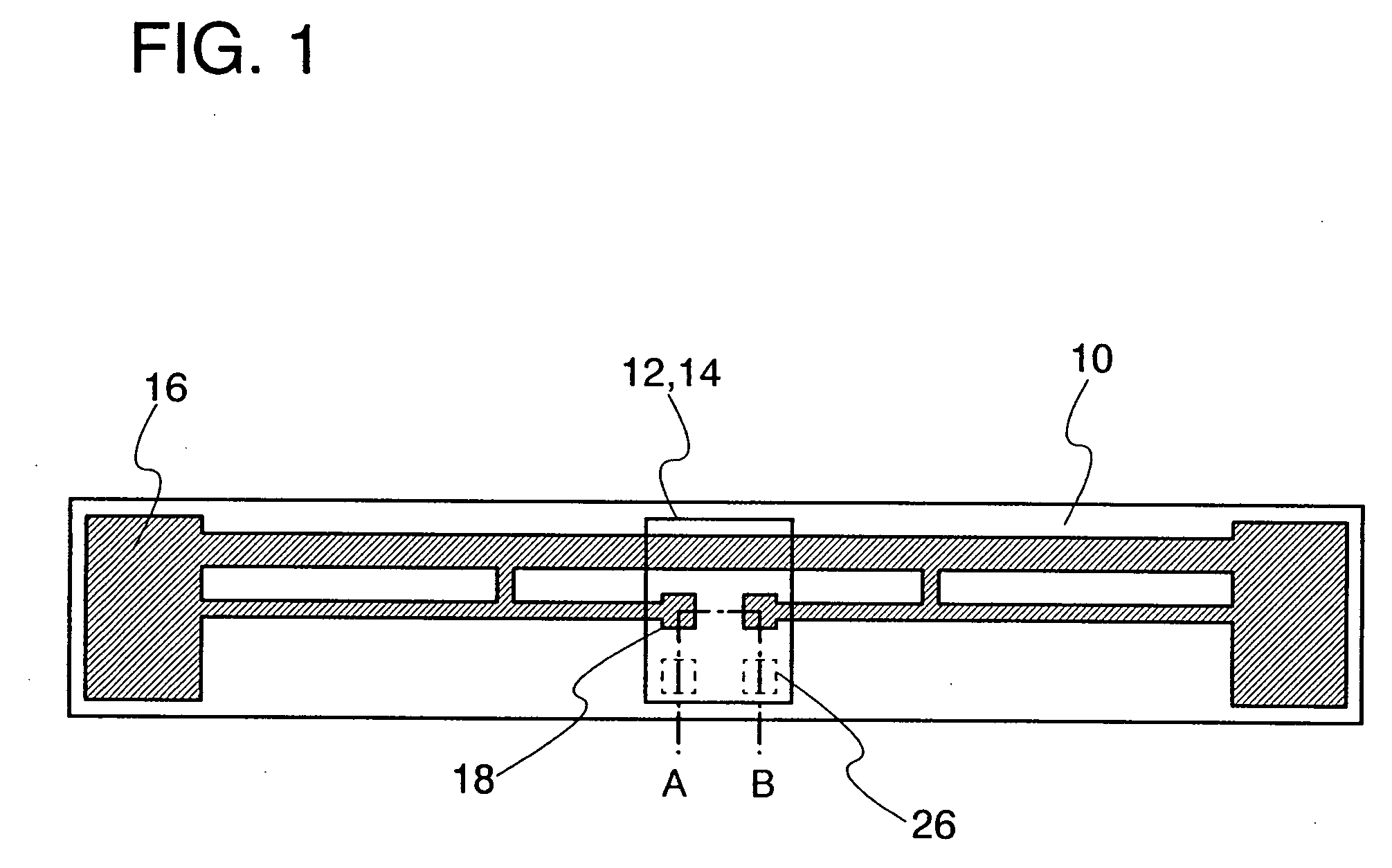
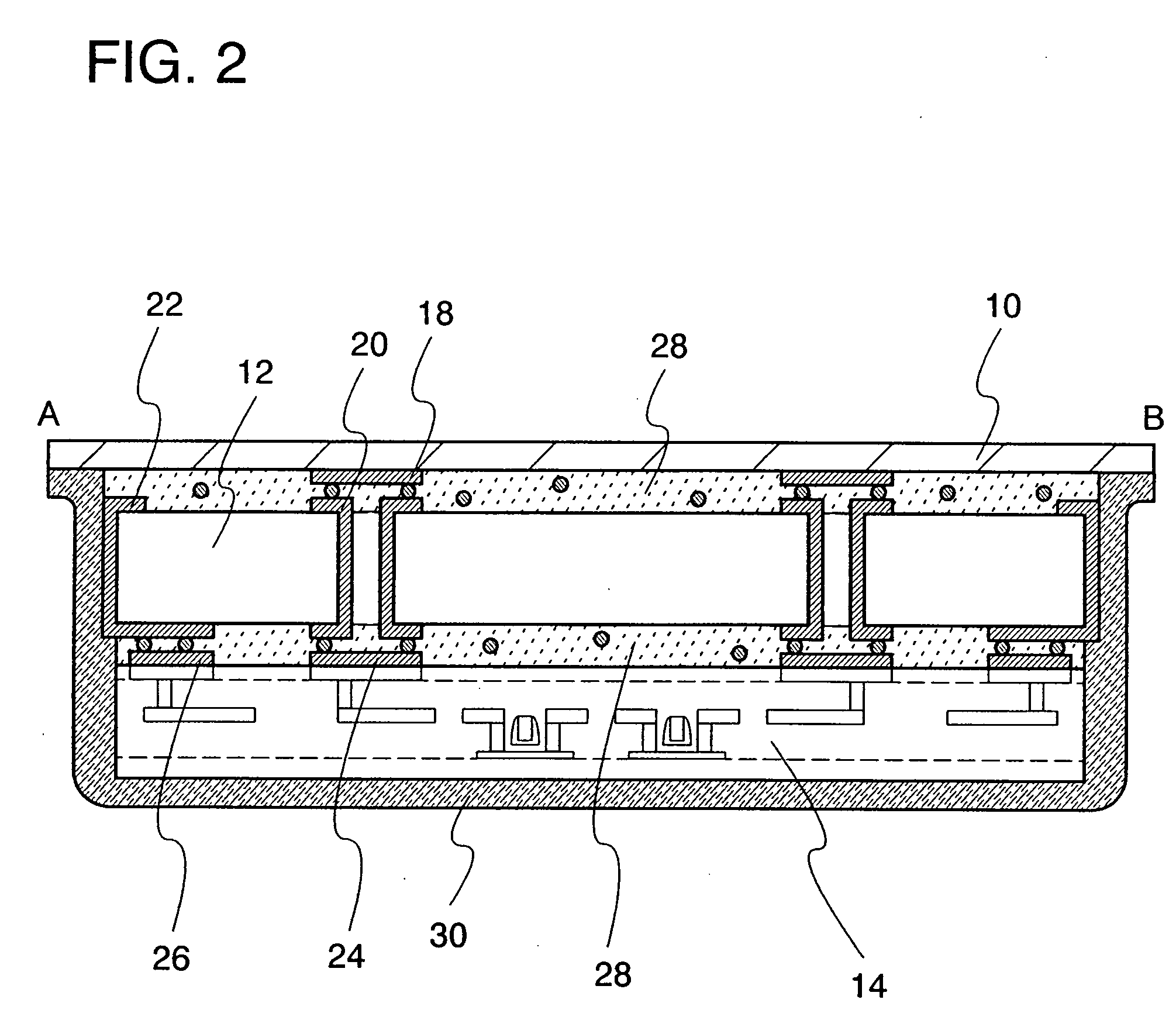
[0050]This embodiment will explain an example of a power storage device that includes a first structural body provided with an antenna, a second structural body provided with a capacitor, and a power supply control circuit 14, with reference to FIGS. 4A to 4C and FIGS. 5A and 5B. FIGS. 4A to 4C are plan views of the power storage device, and FIGS. 5A and 5B are cross-sectional views taken along lines A-B and C-D of FIG. 4A.
[0051]FIG. 4A shows a mode in which an antenna 16 having a coil-shape is formed in a first structural body 10. The first structural body 10 is formed using a plastic material such as PET (polyethylene terephthalate), PEN (polyethylene naphthalate), PES (polyethersulfone), polypropylene, polypropylene sulfide, polycarbonate, polyether imide, polyphenylene sulfide, polyphenylene oxide, polysulfone, polyphthalamide, acrylic, or polyimide, or an insulating material such as nonwoven fabric, or paper.
[0052]The antenna 16 is formed in the first structural body 10 using a...
embodiment 2
[0060]This embodiment will explain an example of a power storage device of the present invention provided with a plurality of antennas. An example of a power storage device will be explained with reference to FIGS. 6A to 6D and FIGS. 7A and 7B, which includes a first structural body 10 provided with an antenna, a second structural body 12 provided with a capacitor, a power supply control circuit 14, and a ceramics antenna 38. FIGS. 6A to 6D are plan views of the power storage device, and FIGS. 7A and 7B are cross-sectional views taken along lines E-F and G-H.
[0061]In FIG. 6A, an antenna 16 having a coil-shape is formed in the first structural body 10. The shape of the antenna 16 may be appropriately set in accordance with a frequency band that is used for communication, similarly to in Embodiment 1.
[0062]FIG. 6A shows a mode in which the second structural body 12, the power supply control circuit 14, and the ceramics antenna 38 are provided in accordance with an antenna terminal 18....
embodiment 3
[0068]An example of a power supply control circuit of a power storage device of the present invention will be explained with the use of a block diagram shown in FIG. 8.
[0069]A power storage device 100 of FIG. 8 includes an antenna 102, a power supply control circuit 104, and a capacitor 106. The power supply control circuit 104 includes a rectifier circuit 108, a low-frequency signal generation circuit 110, a switching circuit 112, and a power supply circuit 114. Power is output from the power supply circuit in the power supply control circuit to a load 118 on the outside of the power storage device.
[0070]The antenna 102 is formed in the first structural body 10 in accordance with Embodiment 1. The capacitor 106 is formed in the second structural body 12. The power supply control circuit 104 corresponds to the power supply control circuit 14.
[0071]A structure of the load 118 in FIG. 8 is different depending on electronic devices. For example, in the cellular phones and the digital v...
PUM
 Abstract
Description
Claims
Application Information
 - R&D
- Intellectual Property
- Life Sciences
- Materials
- Tech Scout
- Unparalleled Data Quality
- Higher Quality Content
- 60% Fewer Hallucinations
Browse by: Latest US Patents, China's latest patents, Technical Efficacy Thesaurus, Application Domain, Technology Topic, Popular Technical Reports.
© 2025 PatSnap. All rights reserved.Legal|Privacy policy|Modern Slavery Act Transparency Statement|Sitemap|About US| Contact US: help@patsnap.com


