
Amplifier circuits, methods of starting and stopping amplifier circuits

a technology of amplifier circuits and amplifiers, applied in push-pull amplifiers, phase-splitters, gain control, etc., can solve the problems of high silicon area and associated cost, known measures also do not address a further source of transients, associated startup transients, etc., to achieve accurate matching of components, reduce or eliminate transients or ‘pop’

Active Publication Date: 2008-01-31
CIRRUS LOGIC INC
View PDF17 Cites 28 Cited by
  • Summary
  • Abstract
  • Description
  • Claims
  • Application Information

AI Technical Summary

Benefits of technology

[0007]The invention has a first object to reduce or eliminate transients or ‘pop’ associated with the start-up of an amplifier circuit, while reducing the need for accurately matched components with their associated size and cost penalty. The invention in particular aims to correct errors in amplifiers having unequal ground reference levels for input and output stages. Start-up transients are a problem in applications other than audio applications, and so the invention is not limited to audio applications even though the examples to be described may be primarily audio examples.
[0010](b) with the biasing circuit effectively disabled and a zero input signal at said signal input, enabling the output stage;
[0019]The invention in either case exploits the dual supply arrangement to provide a novel two-stage start-up procedure in which the matching of components is less critical altogether.

Problems solved by technology

Even with such measures, a problem remains, however, particularly if there is a DC offset at the amplifier output during normal operation.
When the amplifier turns on, the output voltage goes from zero volts to the steady-state offset voltage in a relatively short time period, resulting in a pop.
To achieve low DC offset voltages, accurately matched components and circuits are required, which tends to increase their size, resulting in higher silicon area and associated cost.
The known measures also do not address a further source of transients that has been identified by the inventor.
But any difference between this pre-charge voltage and the output voltage from the output amplifier derived with the bias signal will result in an associated startup transient.
As an alternative to DC coupling and setting the quiescent output level via a bias current injected at the input, AC coupling via capacitors and setting the quiescent output level by local d.c. feedback around the output stage is also possible, but may not be attractive in an integrated circuit implementation.
Furthermore, a local d.c. feedback arrangement also has its own start-up and offset problems.

Method used


Image

  • Amplifier circuits, methods of starting and stopping amplifier circuits
  • Amplifier circuits, methods of starting and stopping amplifier circuits
  • Amplifier circuits, methods of starting and stopping amplifier circuits

Examples


Embodiment Construction

Background

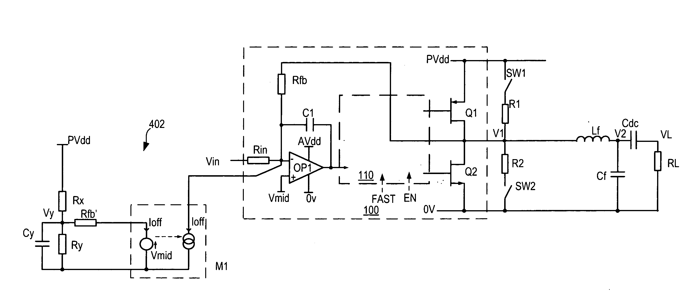
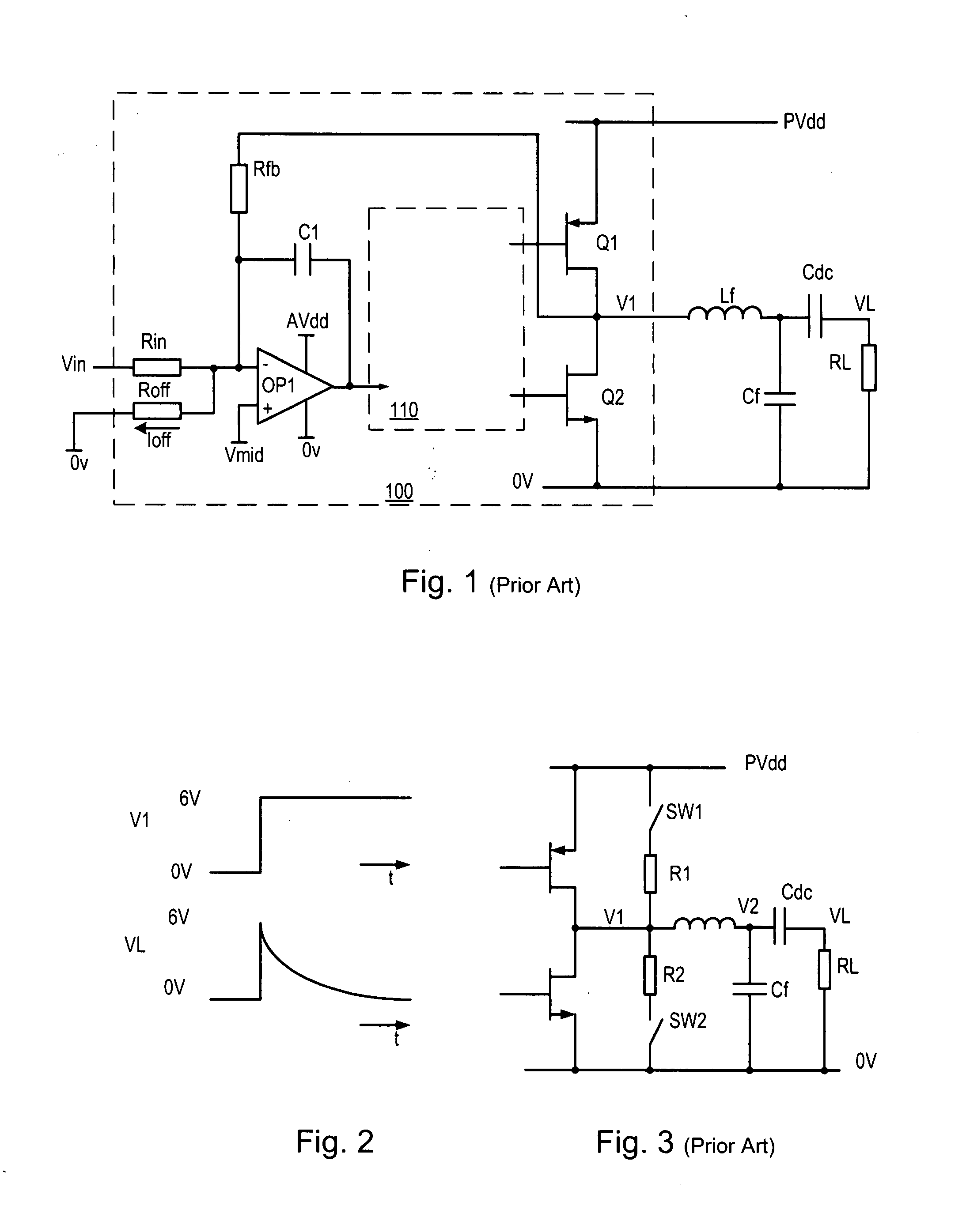
[0056]FIG. 1 shows a classical analogue-input pulse width modulator or class D amplifier 100. For the sake of example only, it is assumed that this amplifier is for driving a loudspeaker or earphones in an audio application. Other applications of amplifiers (particularly PWM amplifiers) include motor control and many others so that the invention is not at all limited to audio applications. The amplifier 100 has an input stage based around operational amplifier (op-amp) OP1. The amplifier also has a switching output (driver) stage formed by output switches (typically power transistors) Q1 and Q2 which switch a PWM output voltage V1 between power supply rails 0V and PVdd. An output filter Lf, Cf is provided to demodulate the audio signal by filtering off high frequency carrier components. In this example the supply is single-ended and a DC blocking capacitor Cdc is provided in series with the load RL, to pass only the wanted audio signal.

[0057]The input stage op-amp OP1 is c...


PUM


Abstract

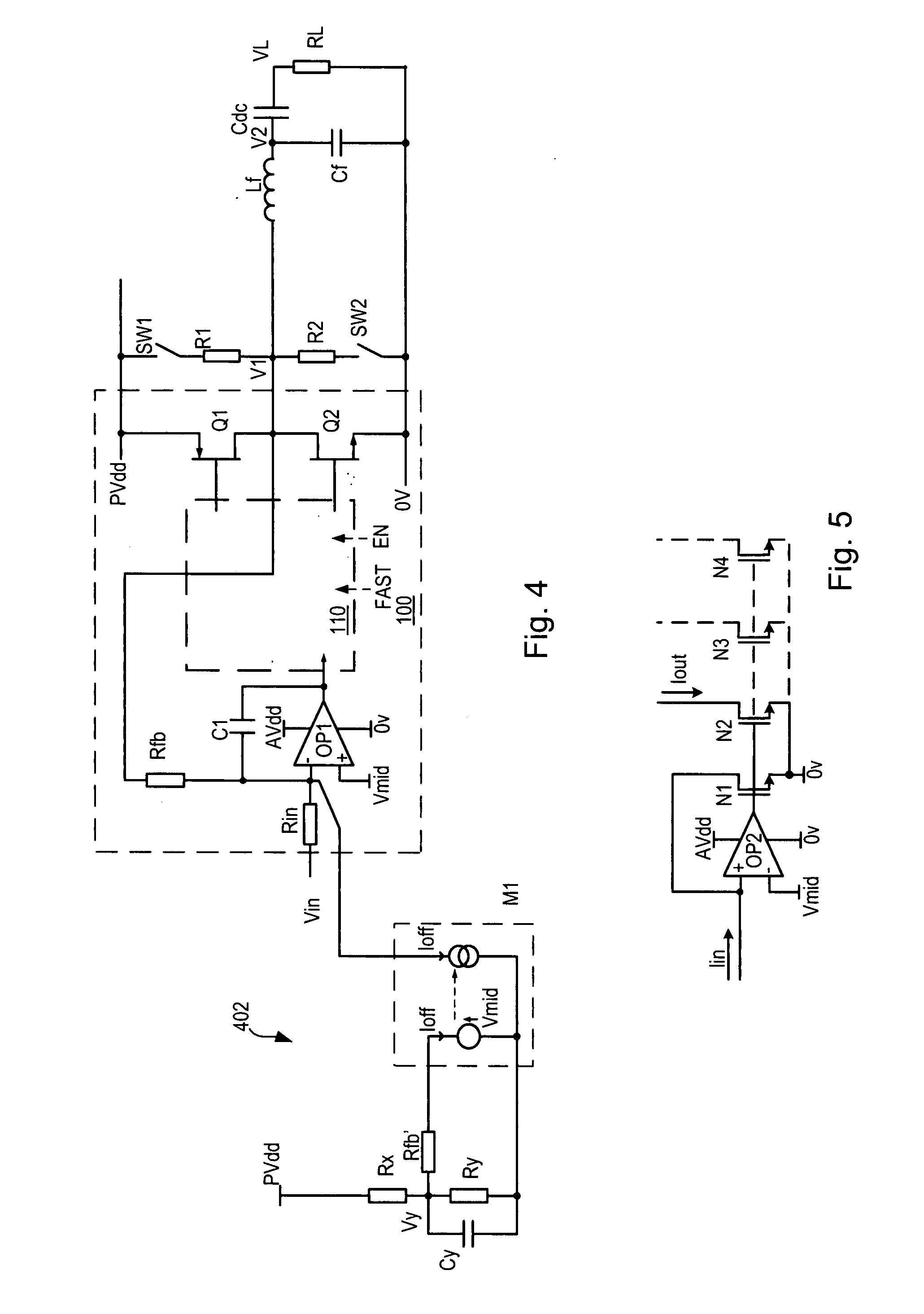
An amplifier circuit (100) has an input stage (OP1) and an output stage (Q1, Q2) operating with different supply voltages and different quiescent voltages. The output stage has a feedback input connected to receive a feedback signal from the output of the output stage. A biasing circuit (602) applies a bias signal (Ioff) to said input stage at an operating level appropriate to establish a quiescent output voltage different from a ground reference level of the input stage. To start up the amplifier with minimal transients at the output, the following steps are performed in sequence: (a) with the output stage disabled, pre-charging the amplifier output over a period of time to a level (Vmid) corresponding to the ground reference level of the input stage; (b) with the biasing circuit effectively disabled and a zero input signal at said signal input, enabling the input and output stages; (c) activating said biasing circuit progressively so as to ramp said bias signal (Ioff) to said operating level over a further period of time, thereby driving the output progressively to said quiescent output voltage. A separate improvement is in the biasing circuit, which uses the actual output stage supply voltage (PVdd) as a reference to define the operating level of said bias signal (Ioff).

Description

FIELD OF THE INVENTION[0001]The invention relates to amplifier circuits, particularly circuits having separate voltage supplies for different stages, or for some other reason having different ground reference levels for different stages. The invention also relates to methods and arrangements for controlling the start-up of such amplifiers while minimizing transients, and to audio and electromechanical apparatus including such amplifiers and methods.BACKGROUND[0002]It is a general requirement of audio circuits that that no audible ‘pops’ or ‘clicks’ occur through the loudspeaker or headphone when the circuit is powered up or powered down. Pops occurring during start-up or shutdown are generally caused by transient voltages across the load. Careful circuit design can avoid many start-up transients, for example by pre-charging capacitors to proper voltages. In Class D (PWM) amplifiers, the pulse train also can be modified at start up by a number of known techniques.[0003]Even with such...

Claims


Application Information

Patent Timeline
IPC IPC(8): H03F1/36
CPCH03F1/305H03F3/217H03F3/3022H03F3/45475H03F2203/30027H03F2200/03H03F2200/351H03F2200/391H03F2200/421H03F3/68
Inventor MAGRATH, ANTHONY JAMES
Owner CIRRUS LOGIC INC
Learn More