
Thermal module system for LED headlamp module

a technology of led headlamps and modules, which is applied in the direction of transportation and packaging, semiconductor devices of light sources, lighting and heating apparatus, etc., can solve the problems of changing the lighting properties, reducing the lifetime of led headlamps, and still many technical necks to be overcome, so as to reduce the ambient air temperature, prolong the lifetime of led headlamps, and reduce heat

Inactive Publication Date: 2008-01-31
IND TECH RES INST
View PDF8 Cites 41 Cited by
  • Summary
  • Abstract
  • Description
  • Claims
  • Application Information

AI Technical Summary

Benefits of technology

[0005]A primary object of the present invention is to provide a thermal module system which is independently located distant from heat-producing elements in a car engine compartment, and lowers the ambient air temperature of the LED headlamp by isolating the heat is produced by the engine compartment from the LED headlamp, so as to extend the lifetime of the LED headlamp.
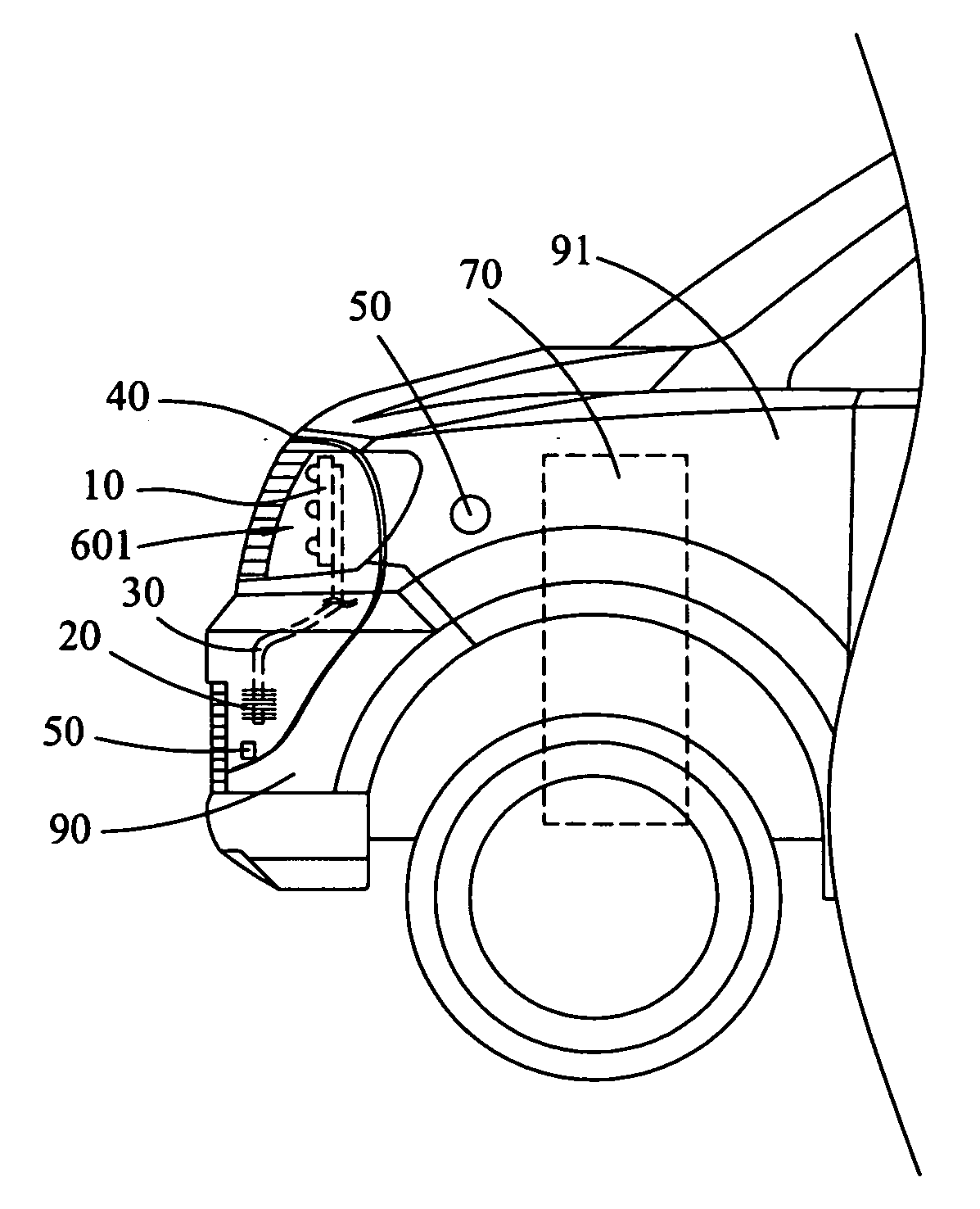
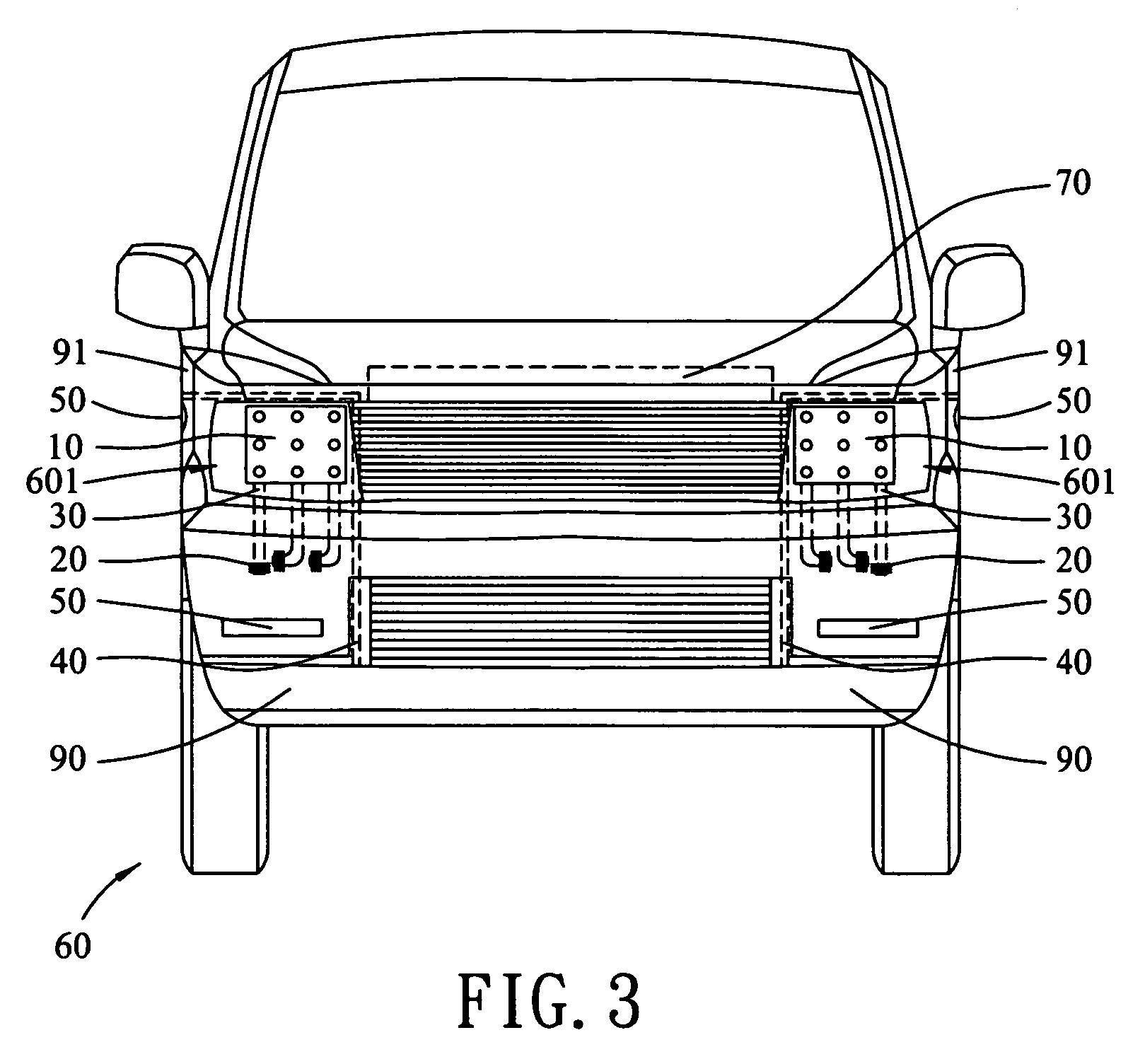
[0006]To achieve the above and other objects, the thermal module system for LED headlamp module according to the present invention includes a thermal module arranged on the car in an air passage, which is distant from heat-producing elements in the engine compartment and has a temperature relatively lower than that of the engine compartment, such as in or behind a front bumper, at an inner side of a front fender of said car, or at a radiator side; a LED module for forming the LED headlamp; and a heat conductive element connected at an end to the heat sink module and at the other end to the LED module to transmit heat produced by the LED module to the heat sink module. Preferably, a heat insulating material is provided around the LED module to supply a space isolated the heat from the engine compartment and thereby reduces the heat being transmitted from the engine compartment and other high-temperature elements to the LED module. That is, the LED module is isolated from heat produced by the engine compartment, while the heat produced by the LED module is transmitted via the heat conductive element to the heat sink module and then dissipated. The air passage has vents provided on the front bumper, the front fender of said car, and / or a clearance around the front fender of said car. The heat insulating material may also be provided around the air passage to further isolate the air passage from heat sources. Since the thermal module is arranged in the air passage, its heat dissipating capacity is enhanced by natural convection of airflow passed through the air passage when the car is in the idle or still state, or by forced convection of air flow passed through the air passage when the car is in the running or moving state. A fan may also be provided near the heat sink module to actively enhance the convection effect. Further, a water sprayer may be provided in the car near the heat sink module to enhance the thermal performance of the thermal module system. With these arrangements, the LED module may work at a lowered ambient air temperature to prolong its lifetime.
[0007]The thermal module system of the present invention has simple structure to enable manufacture at reduced cost. Since the thermal module system for LED headlamp module of the present invention is independently provided in the car, it does not involve in linking or connection to other components. So, the car is easy to facilitate convenient assembly thereof and future maintenance or repair.

Problems solved by technology

While the LED has good potential in the field of car headlamp, there are still many technical necks to be overcome.
However, the increase of temperature also changes the lighting property and shortens the lifetime of LED.
The lighting property of the LED tends to be affected by ambient air temperature.
Therefore, ambient air temperature is a major factor determining the light output and lifetime of the LED, and also a main obstacle in the application of LED in car headlamp.
This is mainly because most existing car headlamps are produced using a lightweight material, and have a low profile to reduce an overall thickness thereof, resulting in a largely reduced space for mounting the headlamp.
Heat produced by the LED together with the great amount of heat from the engine compartment adversely lower the efficiency and lifetime of the LED headlamp.
Among various kinds of electronic products for car being developed in all countries in the world, LED headlamp is most difficult to design due to the thermal problem thereof.

Method used


Image

  • Thermal module system for LED headlamp module
  • Thermal module system for LED headlamp module
  • Thermal module system for LED headlamp module

Examples


Embodiment Construction

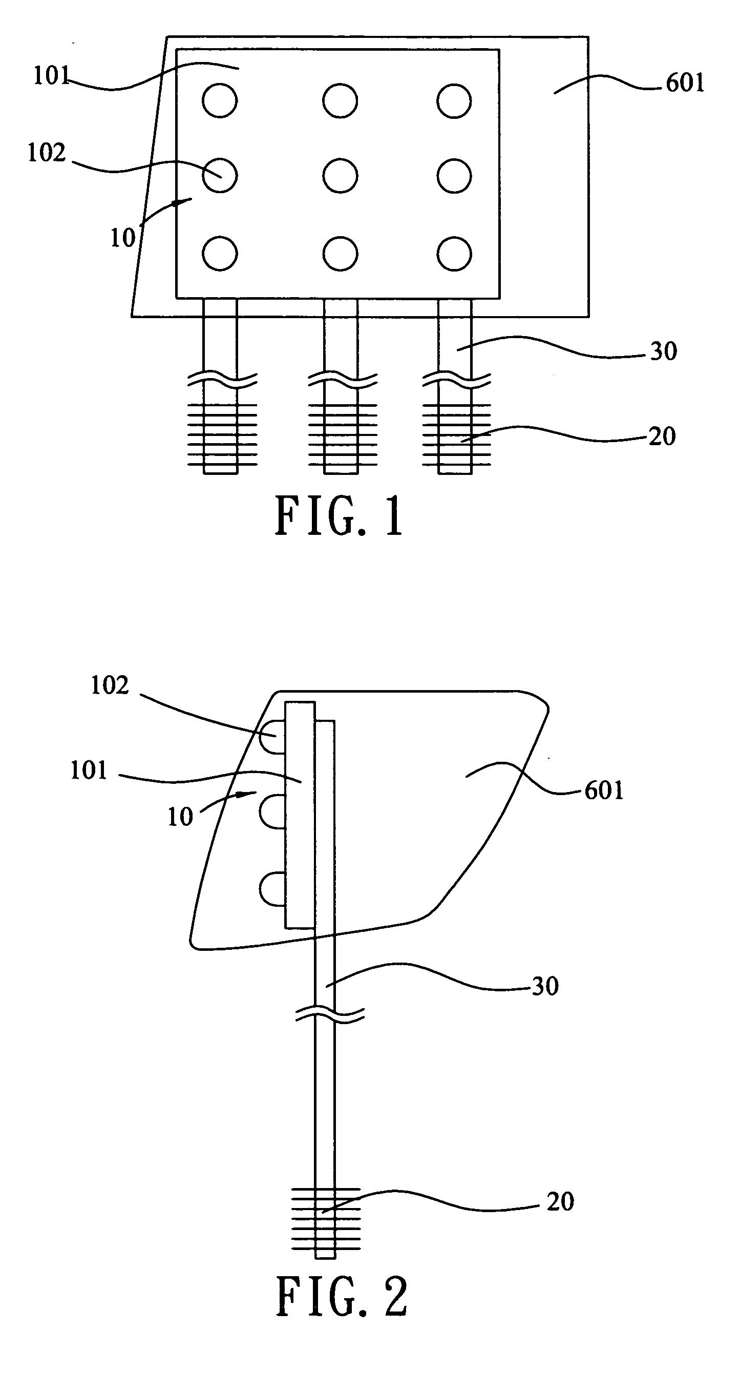
[0017]Please refer to FIGS. 1 and 2 that are front and side views, respectively, of a thermal module system for LED headlamp module according to the present invention. As shown, the thermal module system for LED headlamp module of the present invention includes a LED module 10, at least one heat sink module 20, and at least one heat conductive element 30.

[0018]The LED module 10 is mounted inside a headlamp 601 of a car 60 (not shown in FIGS. 1 and 2), and includes a panel 101 and a plurality of light emitting diodes (LEDs) 102 mounted on the panel 101. When the current is supplied from the car 60 to the LED module 10, the light emitting diode 102 on the panel 101 emit light, which is projected from the headlamp 601 by a reflector in the headlamp 601.

[0019]The heat sink module 20 is arranged in an air passage 50 in the car 60, and is made of a high thermal conductivity material, such as aluminum, copper, etc. The heat sink module 20 is provided with a plurality of fins, which may be ...


PUM


Abstract

A thermal module system for LED headlamp module includes a LED module, heat produced by which is transmitted via a heat conductive element to a heat sink module and dissipated. The heat sink module is arranged in an air passage in a car, such as behind a front bumper, at an inner side of the front fender of said car, or in front of the radiator. Heat insulating material is provided around the LED module to prevent high temperature of an engine compartment from being transmitted to the LED module. The air passage has vents provided on the front bumper and the front fender of said car, so that the heat sink module has enhanced thermal performance due to natural or forced air convection. A fan or water sprayer may be provided near the heat sink module to improve the thermal performance. Therefore, the LED module may work at a lowered ambient air temperature to have a prolonged lifetime.

Description

FIELD OF THE INVENTION[0001]The present invention relates to a thermal module system for light emitting diode (LED) headlamp, and more particularly to a thermal module system for LED headlamp module is capable of lowering ambient air temperature in which a LED headlamp works by isolating the LED headlamp from heat produced in an engine compartment of a car, so that the LED headlamp has a prolonged lifetime.BACKGROUND OF THE INVENTION[0002]The light emitting diode (LED) was first introduced into the world in 1968, and featured by many advantages, including energy-saving, lightweight, long lifetime, low driving voltage, rapid response time, and outstanding shockproof ability. In the seventies of twenty century, the LED was commercialized and most researches thereof were directed to high brightness, multi-color, and high light efficiency. Thereafter, in the eighties, high-brightness GaAsP LED(red) and GaP LED(green) were successively developed. In the nineties, there were also successi...

Claims


Application Information

Patent Timeline
IPC IPC(8): B60Q1/04F21V29/02
CPCB60Q1/0005F21S48/1145F21S48/321F21Y2101/02F21V29/30F21V29/006F21S48/326F21V29/67F21Y2115/10F21S45/43F21S45/46F21S45/49B60Q1/04
Inventor CHIANG, SONG-BOR
Owner IND TECH RES INST
Learn More