Variable stiffness intramedullary stem

a technology of intramedullary stems and stiffness, which is applied in the field of intramedullary stems and implants, can solve the problems of high stress on the skeleton around the tip of the femoral stem, increased risk of fracture, and loss of mass in the upper part of the thighbone, and achieves the effect of variable stiffness

Inactive Publication Date: 2008-01-31
ZIMMER TECH INC
View PDF8 Cites 27 Cited by
  • Summary
  • Abstract
  • Description
  • Claims
  • Application Information

AI Technical Summary

Benefits of technology

[0007]The present invention provides a variable stiffness stem component for intramedullary fixation in total joint replacement implants including knee, hip, and shoulder prosthesis and in a segmental replacement system. The stem component comprises a shaft having a proximal end, a distal end, and a longitudinal length therebetween. The shaft has an approximately constant diameter along the longitudinal length to provide maximal surface area for fixation. The stem component may further comprise a taper or threaded connection adjacent the proximal end of the shaft for assembly to another implant component. Alternatively, the proximal end of the shaft may integrally meet with another

Problems solved by technology

First, due to reduced stress levels, the upper part of the thighbone may lose mass through a process known as osteopenia.
As a result, the bone around the stem may become weaker and more susceptible to fracture.
Second, the skeleton around the tip of the femoral stem component may experience locally high stresses as the load within the stem is transfer to the bone at the stem tip.
Patients

Method used


Image

  • Variable stiffness intramedullary stem
  • Variable stiffness intramedullary stem
  • Variable stiffness intramedullary stem

Examples


example

[0025]The following example is provided to illustrate the invention and is not intended to limit the same.

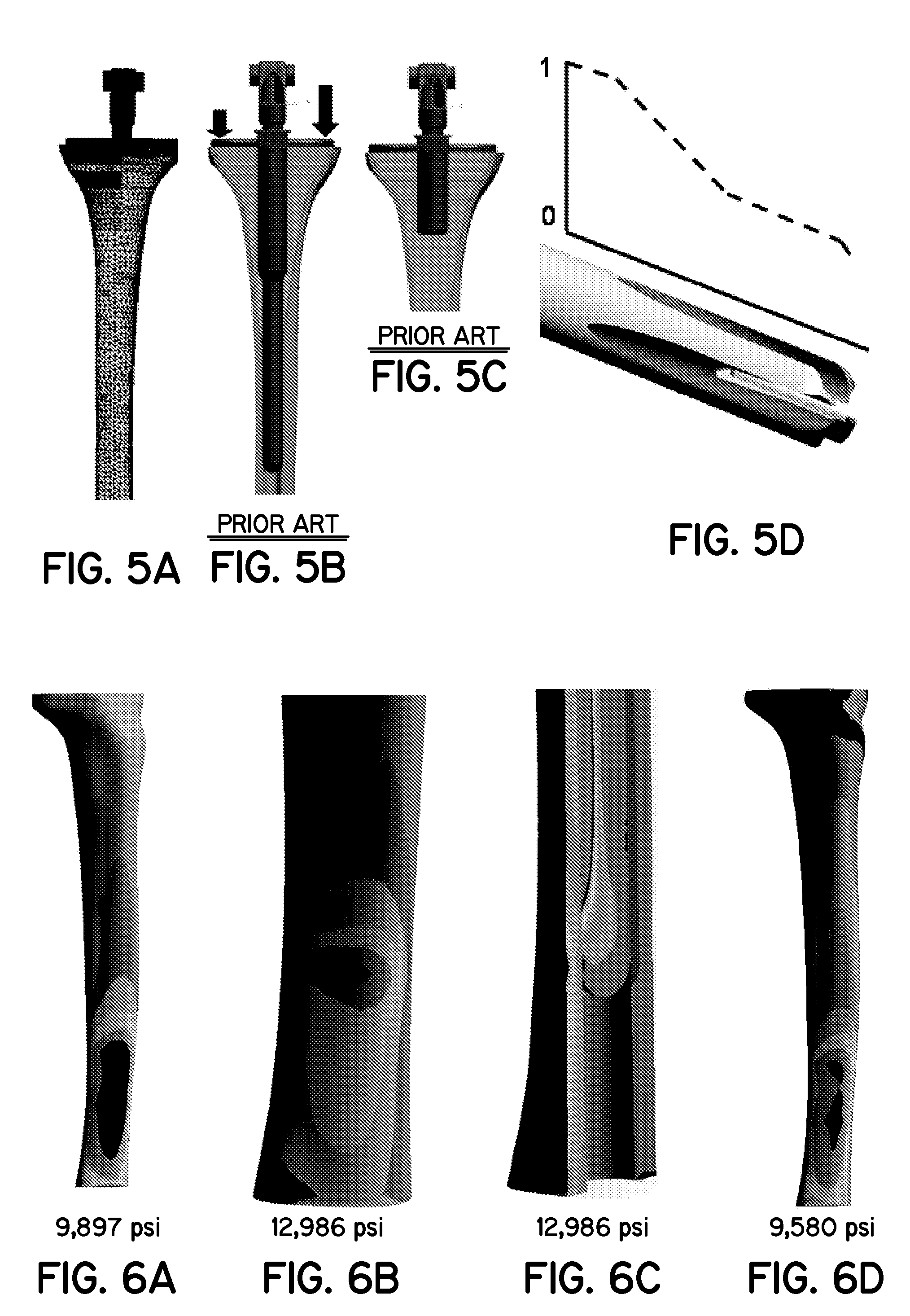
[0026]Three dimensional, finite element stress analysis models of the proximal tibia with total knee replacement (TKR) implants subjected to joint loading associated with a constrained implant in mid-stance gait (FIGS. 5A-D) were developed. As depicted in FIG. 5A, the models were constructed utilizing approximately 130,000 tetrahedral and 35,000 contact elements. The bone of the proximal tibia was modeled as a linearly elastic material with a spatial distribution of the modulus of elasticity of trabecular bone. The prosthesis-to-bone interface was modeled as bonded under the tibial tray and as press fit along the stem with an experimentally determined coefficient of friction. The implant components were modeled as constructed of cobalt alloy. Several tibial stem component design features were parametrically modeled ranging from a 175 mm solid cylindrical stem (FIG. 5B), a 35 mm ...


PUM


Abstract

A variable stiffness stem component for intramedullary fixation in total joint replacement implants or in a segmental replacement system. The stem component has a shaft with a proximal end, a distal end, and a longitudinal length therebetween. The diameter of the shaft is approximately constant along the longitudinal length. A taper or threaded connection may be provided adjacent the proximal end of the shaft for assembly to another implant component. At least three flutes are disposed in a portion of the length of the shaft from intermediate the proximal and distal ends extending towards the distal end. The flutes increase in one of width or depth, or a combination thereof, towards the distal end to provide variable stiffness.

Description

FIELD OF THE INVENTION[0001]The present invention relates generally to devices for arthroplasty and bone segment replacement and specifically to intramedullary implants and stems.BACKGROUND[0002]Artificial joints are generally ball and socket or hinge joints designed to match as closely as possible the function of the natural joint. To duplicate a joint's natural motion, a total joint replacement implant often includes a bearing surface component, such as a spherical ball to replace the head of the femur, and a component which fits into the intramedullary canal of the femur, tibia, or humerus to provide stability for the bearing surface.[0003]The stem component may also be used in the replacement of segments of the long bones of the upper or lower extremity. The bone segment application most likely occurs due to the treatment of bone tumors or cancer.[0004]The presence of a stemmed prosthetic component in the intramedullary canal can be expected to change the distribution of stress ...

Claims


Application Information

Patent Timeline
IPC IPC(8): A61F2/36A61B17/72
CPCA61B17/7208A61F2310/00029A61F2/3662A61F2/3676A61F2/38A61F2002/30014A61F2002/30179A61F2002/30224A61F2002/30326A61F2002/30332A61F2002/30535A61F2002/30604A61F2002/3082A61F2002/30827A61F2002/30828A61F2002/30879A61F2002/365A61F2002/3652A61F2002/3654A61F2002/4011A61F2220/0033A61F2230/0058A61F2230/0069A61F2250/0018A61F2250/0037A61F2250/0058A61F2250/006A61F2310/00017A61F2310/00023A61B17/7283
Inventor CROWNINSHIELD, ROYWENTZ, DOUGLASSTOLLER, ALEX P.
Owner ZIMMER TECH INC
Why Eureka
Try Eureka