Light emitting apparatus

a technology of light-emitting apparatus and light-emitting tube, which is applied in the direction of lighting and heating apparatus, discharge tube luminescnet screen, semiconductor laser, etc., can solve the problems of deterioration of organic binder resin itself, large reduction of emission brightness, and inability to obtain sufficient weather resistance and reliability in the method of sintering, etc., to achieve superior weather resistance and reliability, and high emission intensity

Active Publication Date: 2008-02-07
NICHIA CORP
View PDF4 Cites 59 Cited by
  • Summary
  • Abstract
  • Description
  • Claims
  • Application Information

AI Technical Summary

Benefits of technology

[0009]The objective of the present invention is to provide a light emitting apparatus having a wavelength-converting member that has high emission intensity and that is superior in weather resistance and reliability.

Problems solved by technology

However, in a light emitting device using a light emitting diode etc., when a wavelength-converting member is constituted with a phosphor layer containing an organic binder resin, the organic binder resin itself deteriorates by light of high output in the short wavelength region (the ultraviolet region to the blue region) and there is a problem that emission brightness decreases largely by coloring, etc.
However, there is a case that sufficient weather resistance and reliability cannot be obtained in the method of sintering and removing the organic binder resin.
Further, in the case of sintering at high temperature, the phosphor deteriorates or decomposes depending on the type of the phosphor, and there is a case that the emission intensity decreases.
Further, also in the case of dispersing the phosphor into a glass, the phosphor deteriorates or decomposes because the process temperature becomes high, and there is a case that the emission intensity decreases.

Method used


Image

  • Light emitting apparatus
  • Light emitting apparatus

Examples


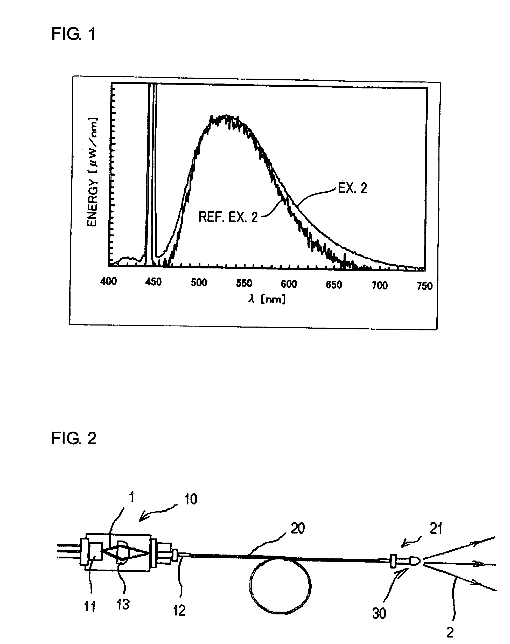
examples 1 to 9 and reference examples 1 to 3

[0049]A wavelength-converting member was manufactured using the phosphor and the glass material shown in Table 1 at the compounding ratio shown in Table 1. Specifically, a wavelength-converting member was obtained by sufficiently mixing the phosphor and the glass material shown in Table 1 with a mixing machine and a dry method, filling a crucible with this raw material, calcining it at 540° C. for 20 minutes in an air atmosphere, and molding it into a fixed shape. Moreover, it was heated and calcined at 540° C. for 20 minutes in Reference Example 3.

[0050]A LAG phosphor (an aluminate phosphor) of the composition shown below and a CASBN phosphor (a nitride phosphor) of the composition shown below were used as the phosphor.

[0051]LAG phosphor: (Lu0.94)3Al5O12: Ce0.06

[0052]CASBN phosphor: Ca0.99Al1.00Si1.00B0.10N3.1: Eu0.01

[0053]Further, “glass in the present invention” having a composition in the range of the present invention shown below and “comparison glass” having a composition ou...


PUM

PropertyMeasurementUnit
mole percentageaaaaaaaaaa

Abstract

A light emitting apparatus with high emission intensity and that is superior in weather resistance and reliability is obtained. The light emitting apparatus includes a light source and a wavelength-converting member for converting the wavelength of light emitted from the light source, wherein the wavelength-converting member contains a phosphor subjected to a cleaning treatment and / or a coating treatment, in a glass material having a composition of SiO2: 30 to 50%, Li2O: 0 to 15%, Na2O: 0 to 10%, K2O: 0 to 10%, Li2O+Na2O+K2O: 20 to 30%, B2O3: 5 to 15%, MgO: 0 to 10%, BaO: 0 to 10%, CaO: 0 to 10%, SrO: 0 to 10%, Al2O3: 0 to 10%, ZnO: 0 to 15%, TiO2: 10 to 20%, Nb2O5: 1 to 5%, La2O3: 0 to 5%, and TiO2+Nb2O5+La2O3: 11 to 20% by mole percentage.

Description

BACKGROUND OF INVENTION[0001]1. Field of the Invention[0002]The present invention relates to a light emitting apparatus having a wavelength-converting member using a phosphor.[0003]2. Description of the Related Art[0004]In a wavelength-converting member using a phosphor, light is emitted by mixing phosphor powder, for example, with a molding resin consisting of an organic or an inorganic binder resin that shields a light emitting face of a light emitting element, molding the mixture, absorbing a light emission of the light emitting element, and transforming it to a fixed wavelength. However, in a light emitting device using a light emitting diode etc., when a wavelength-converting member is constituted with a phosphor layer containing an organic binder resin, the organic binder resin itself deteriorates by light of high output in the short wavelength region (the ultraviolet region to the blue region) and there is a problem that emission brightness decreases largely by coloring, etc....

Claims


Application Information

Patent Timeline
Patent Type & Authority Applications(United States)
IPC IPC(8): F21V9/16H01L33/50H01L33/58
CPCC03C3/064C03C3/089C03C3/095C03C4/12H01S5/02284C09K11/0883C09K11/7721C09K11/7734C09K11/02H01S5/02251H01S5/0087C09K11/77348
Inventor MURAZAKI, YOSHINORISATO, YOSHIKI
Owner NICHIA CORP
Why Eureka
Try Eureka