Method and system for interpreting tubing data

a tubing data and data processing technology, applied in the field of processing data, can solve the problems of reducing the responsiveness of the signal, affecting the accuracy of the data,

Active Publication Date: 2008-02-14
KEY ENERGY SERVICES
View PDF9 Cites 39 Cited by
  • Summary
  • Abstract
  • Description
  • Claims
  • Application Information

AI Technical Summary

Benefits of technology

[0017]In one aspect of the present invention, an instrument, scanner, or sensor can monitor tubing, tubes, pipes, rods, hollow cylinders, casing, conduit, collars, or duct near a wellhead of the oil well. The instrument can comprise a wall-thickness, rod-wear, collar locating, crack, imaging, or pitting sensor, for example. As a field service crew extracts tubing from the oil well or inserts the tubing into the well, the instrument can evaluate the tubing for defects, integrity, wear, fitness for continued service, or anomalous conditions. The instrument can provide tubing information in a digital format for example as digital data, one or more numbers, samples, or snapshots. A computer-implemented method can process the tubing data to evaluate whether one or more components of the data is valid, credible, or erroneous or to assign a confidence indicator to the data. For example, validating the data can comprise determining whether any features, structures, or patterns present in the data correlate with actual tubing defects or were caused by a condition unrelated to tubing qualify, such as signal noise or rig speed. The computer-implemented method can also analyze the data to deduce information about the performance of the well or to determine the well's operating state, status, or condition. For example, the data analysis can determine whether the well's fluids have a chemical condition that should be treated or whether a detrimental harmonic oscillation has been occurring in the well's mechanical pumping system. Moreover, the product of the data analysis can comprise a data interpretation, an identification of a data inconsistency, an inference, a deduction, a diagnosis of the well, or a recommended procedure for addressing an identified problem, to name a few possibilities.

Problems solved by technology

The crew typically replaces sections that exhibit an unacceptable level of wear and notes other sections that are beginning to show wear and may need replacement at a subsequent service call.
The transducer and its associated electronics may have a dampened or lagging response that tends to reduce the responsiveness of the signal to tubing wall variations and / or noise.
Meanwhile, the speed of the tubing passing through the measurement zone may fluctuate or change erratically.
Distance between samples may vary, fluctuate, or change erratically as the operator changes the tubing speed.
Moreover, sample data may blur or become smeared when the tubing is moving rapidly.
Consequently, fixing the time interval between each snapshot and allowing the tubing speed to vary between snapshots, as occurs in most conventional instruments, can produce data that is difficult to interpret or fails to adequately characterize the tubing.
Another shortcoming of conventional instruments is that they generally provide an insufficient or limited level of processing of the digital samples.
When the tubing is moving slowly through the instrument's measurement zone or is stationary, an operator may incorrectly interpret variation in the digital samples as a wall defect; however, the variation may actually result from an extraneous effect or signal noise.
At slow tubing speeds, signal spikes due to noise or a random event can be mistaken for a defective tubing condition.
Meanwhile, when the tubing is moving quickly through the measurement zone, the tubing motion may blur or smooth signal spikes that are actually due to tubing defects, thereby hiding those defects from operator observation.
Conventional technologies often fail to differentiate between signal features that indicate the presence of valid tubing defects and other signal features caused by phenomena unrelated to tubing defects.
An observer may struggle to determine with confidence whether actual tubing defects are associated with signal anomalies, for example.
Beyond the limitations associated with validating tubing data, conventional instrumentation technologies typically provide little or no capabilities for data interpretation.
A well may have a chemical condition that causes tubing corrosion or that negatively impacts production.
The sucker rods may exhibit harmonic oscillations that cause premature tubing wear, also inhibiting production.
Identifying these or other well conditions is generally difficult using conventional techniques for presentation and manual review of tubing data.

Method used


Image

  • Method and system for interpreting tubing data
  • Method and system for interpreting tubing data
  • Method and system for interpreting tubing data

Examples


Embodiment Construction

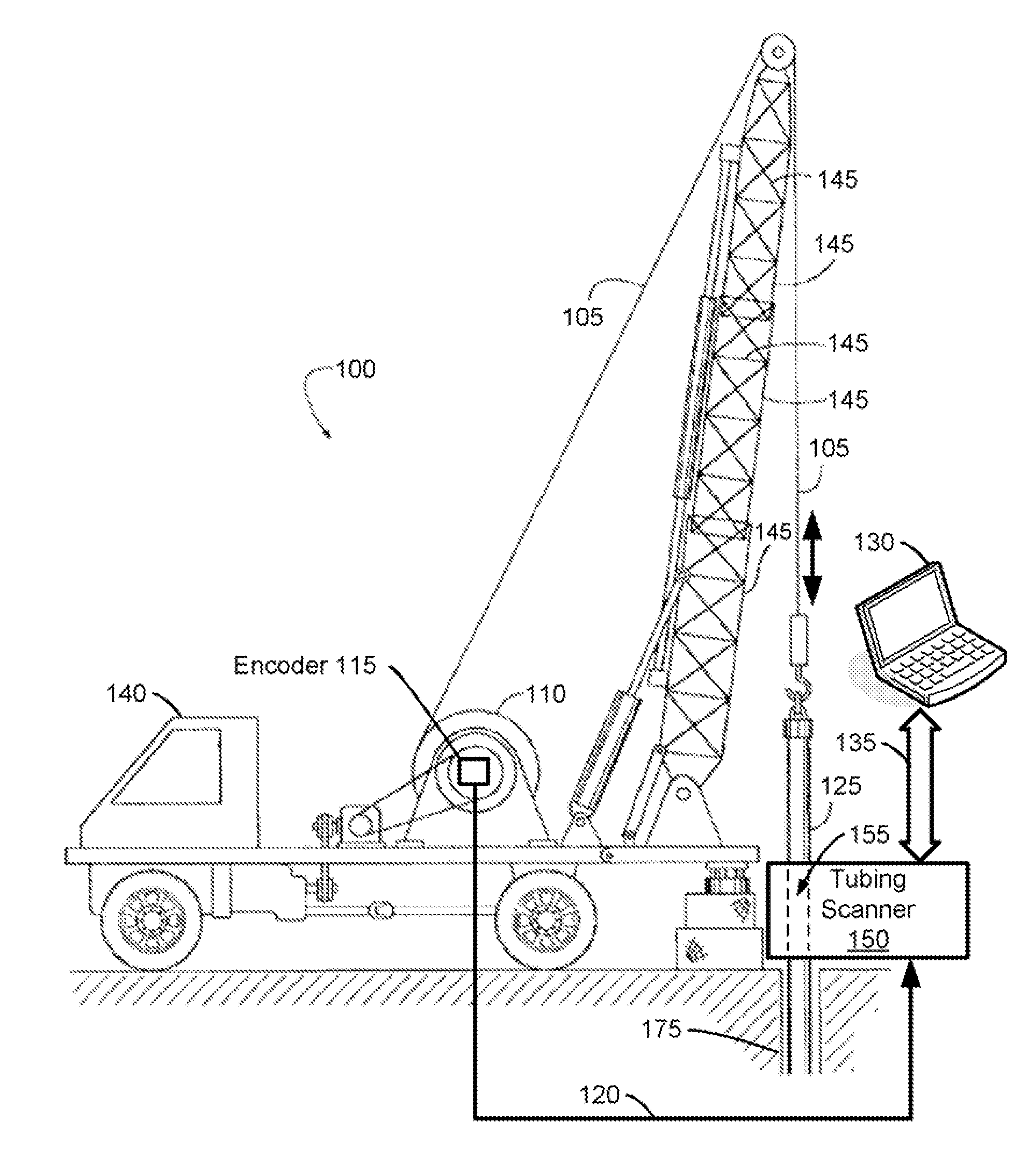
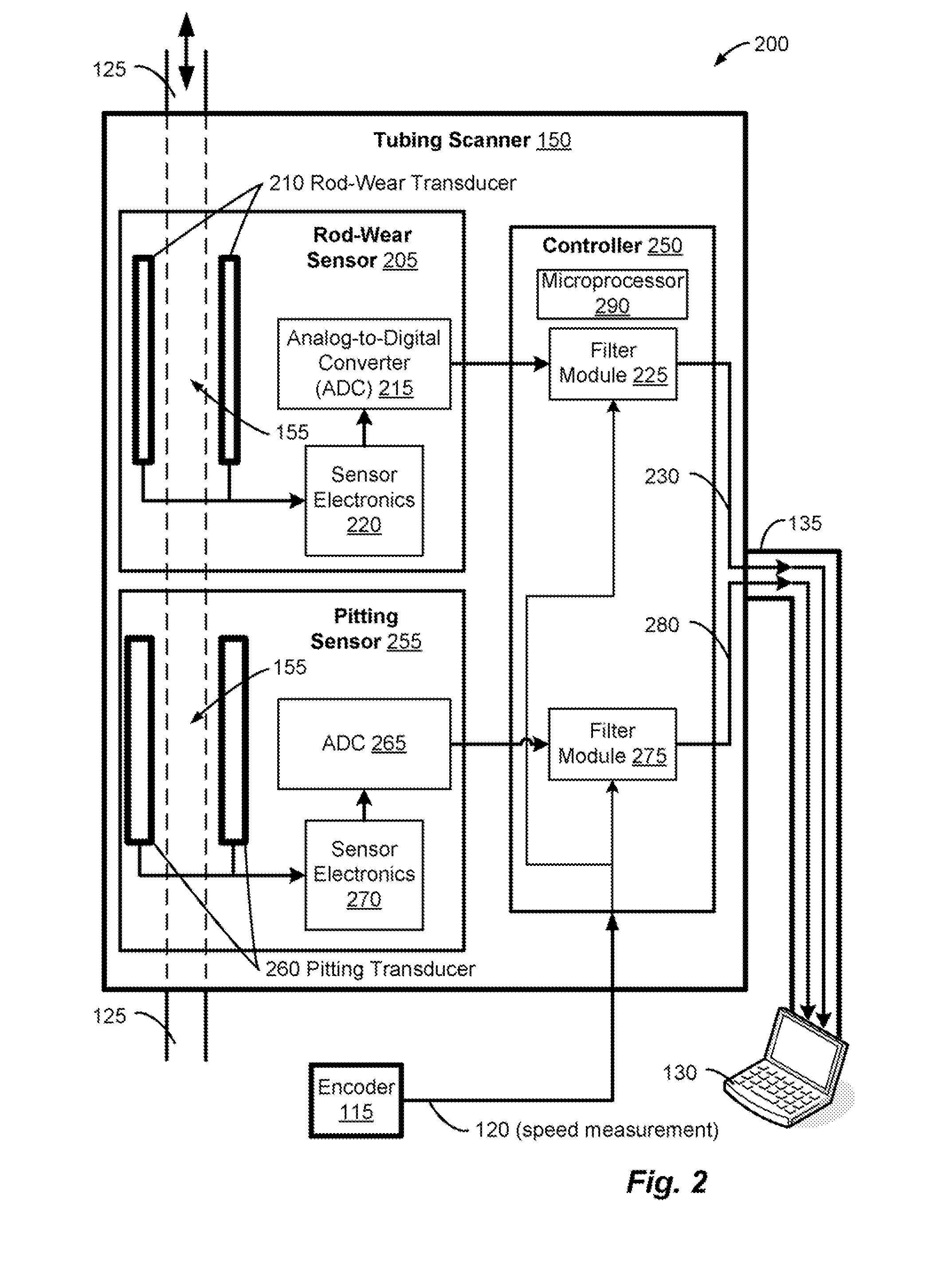
[0045]To more adequately describe the present invention, the Detailed Description has been broken up into three sections. In Section I, the present invention supports processing information or data that describes or characterizes a tubing parameter, such as pitting, wall thickness, wall cracks, or some other indication of tubing quality or integrity. Processing the tubing data can comprise validating and / or interpreting the data. A validation procedure can evaluate whether the data is indicative of an actual tubing defect. An interpretive method can identify and / or diagnosis well conditions, such as a chemical problem or a detrimental harmonic oscillation of a reciprocating sucker rod.

[0046]In Section II, the present invention supports processing information or data that describes or characterizes a tubing parameter, such as pitting, wall thickness, wall cracks, or some other indication of tubing quality or integrity. Processing tubing data can enhance the utility, usefulness, or fi...


PUM


Abstract

An Instrument, such as a wail-thickness, rod-wear, or pitting sensor, can monitor tubing as a field service crew extracts the tubing from an oil well or inserts the tubing into the well. A computer-based system can process data from the instrument to evaluate the validity of the data. Validating the data can comprise determining whether any features, structures, or patterns present in the data correlate with actual tubing defects or were caused by a condition unrelated to tubing quality, such as signal noise. The computer-based system can also analyze the data to deduce information about the performance of the well or to determine the well's operating state or status. For example, the data analysis can determine whether the well's fluids have a chemical condition that should be treated or whether a detrimental harmonic oscillation has been occurring in the well's mechanical pumping system.

Description

[0001]This application claims benefit of U.S. Provisional Application Ser. Nos. 60 / 786,252, filed on Mar. 27, 2006; 60 / 786,272, filed on Mar. 27, 2006; and 60 / 786,273, fled on Mar. 27, 2006.FIELD OF THE INVENTION[0002]The present invention relates to processing data describing a tube associated with an oil well and more specifically to inferring information, such as a condition of the well or the validity of the data, based on processing the data.BACKGROUND[0003]After drilling a hole through a subsurface formation and determining that the formation can yield an economically sufficient amount of oil or gas, a crew completes the well. During drilling, completion, and production maintenance, personnel routinely insert and / or extract devices such as tubing, tubes, pipes, rods, hollow cylinders, casing, conduit, collars, and duct into the well. For example, a service crew may use a workover or service rig to extract a string of tubing and sucker rods from a well that has been producing p...

Claims


Application Information

Patent Timeline
Patent Type & Authority Applications(United States)
IPC IPC(8): E21B47/00
CPCE21B17/00E21B2041/0028E21B41/00E21B2200/22G01N33/20
Inventor NEWMAN, FREDERIC M.
Owner KEY ENERGY SERVICES
Why Eureka
Try Eureka