
Vehicle Transmission Comprising A Parking Brake And Method For Controlling The Same

a technology for vehicle transmissions and brakes, which is applied in the direction of braking systems, instruments, analogue processes for specific applications, etc., can solve the problems of mechanical strain on the affected components of the transmission, unsatisfactory noise, and the possibility of constructing the same friction locking shifting element for the restraint of the driv

Inactive Publication Date: 2008-02-14
ZF FRIEDRICHSHAFEN AG
View PDF3 Cites 28 Cited by
  • Summary
  • Abstract
  • Description
  • Claims
  • Application Information

AI Technical Summary

Benefits of technology

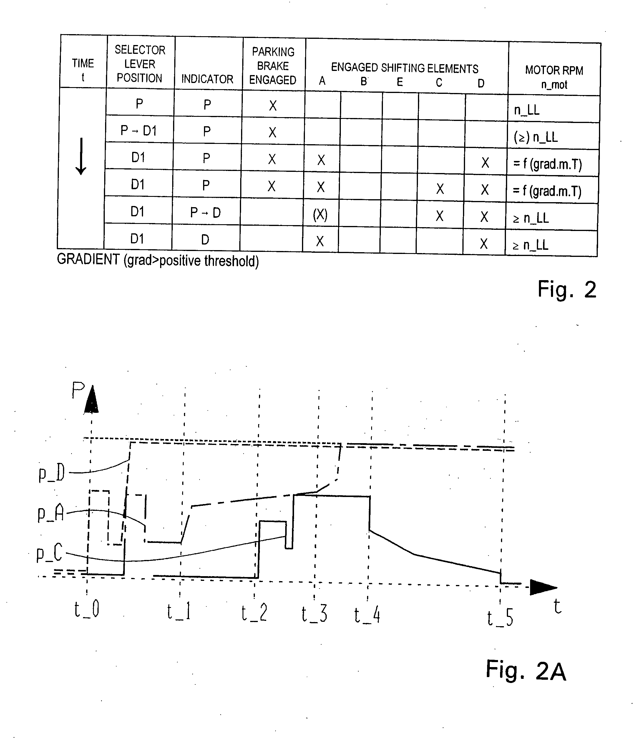
[0011] Finally, it is possible with the method, according to the invention, of temporarily locking the output of a drive train of the vehicle in an advantageous manner when the parking brake, which has been previously activated or engaged for the restraint of the drive, is released by way of at least one engaged friction locking shifting element of the vehicle transmission. This step of the method is especially important when the shifting elements previously activated to slip for releasing strain on the positively locked locking element of the parking brake results in the output of the vehicle rotating in a direction which does not correspond to the rotational direction of the output or of the driving direction corresponding to the driver controlled action. During the mechanical release or disengagement of the parking brake, the output of the vehicle is held by the frictional connection of the locked, frictionally locking shifting elements. If the parking brake is mechanically released or disengaged, the strain on the output can be reduced through a subsequent controlled or regulated disengagement of one of the previously engaged frictionally locking shifting elements without a noticeable release jolt. Simultaneous with the disengagement of the shifting element, engaged for restraining the output, a shifting element combination, which corresponds to the driving gear desired by the driver, is engaged so that, after the disengagement of the locking shifting element, the output can again rotate in the direction corresponding to the driver controlled action.
[0012] This method step, in which the output of the vehicle is held by frictionally locking shifting elements of the transmission on the transmission housing, can be dispensed with, if the vehicle can be driven in the direction intended by the driver with the shifting elements that have previously been made to slip for the reduction of strain on the engaged positive locking element of the parking brake.
[0020] With the method according to the invention, torque stemming from a downhill-slope force-dependent strain on the output is effectively reduced during deactivation or disengagement of the previously activated or engaged positive parking brake, such that a release jolt, caused by the release of the positive locking of the parking brake, is avoided, at least in most operational conditions of the vehicle. During the mechanical release of the positively locked parking brake, if the output of the vehicle is additionally locked by frictionally locking, to the transmission housing, the shifting element of the transmission which is engaged to secure the output, the possibility also exists of reducing the strain over time, of the strained part of the output by a controlled or regulated disengagement of this shifting element and, if appropriate, to select a shifting element combination simultaneously or shortly before release through which comfortable drive of the vehicle in the driving direction desired by the driver is possible.
[0022] Especially advantageous is the combination of the method according to the invention with a so-called “E-shifter” in which the working connection between the driver-operable gearshift and the transmission, is configured as an electrical connection. If a mechanical connection is provided between the driver-operable gearshift and the transmission, for example by way of a Bowden cable, it is also sensible to additionally install a mechanical, electromagnetic or electrohydraulic in the region of the parking brake to prevent the immediate mechanical release of the contact of the parking brake or the immediate mechanical disengagement of the locking element of the parking brake (usually a pawl) when the gearshift is moved to release the parking brake. Such an additional installation in the transmission can, for example, be arranged in a power flow direction between the Bowden cable and the mechanical pulling rod in the parking brake locking element, an electromagnet acting directly on the locking element or an electrohydraulic-activated hydraulic piston acting directly on the locking element. An additional installation in the gearshift can be a braking electromagnet, for example, acting directly on the gearshift, which prevents shifting the gearshift after biasing the gearshift in the direction of the position following the position “P” long enough that the locking element of the parking brake is released by temporarily engaging the frictionally locking shifting elements of the transmission.

Problems solved by technology

In vehicles, the drive trains of which are configured with a hydrodynamic torque converter or a hydrodynamic clutch, this possibility does not apply since, with a turned off motor, a connection between the motor, with its braking power, and the drive cannot be maintained.
When the parking brake is disengaged, the strain of the drive train, which is passed by the chassis of the vehicle above the suspension point of the drive train, is suddenly released with a slight or a strong release join, which is especially pronounced in the case of steep slopes, and is disadvantageous for the driver, on one hand, as an unpleasant jolt and, on the other hand, is also noticeable as an unpleasant noise.
Additionally, it strains the affected components of the transmission mechanically.
If an automatic transmission is already provided with a shifting element for frictionally locking the output, and also necessary for gear shifting and is constructed as a multiple disc clutch or multiple disc brake in the usual manner of construction, the pressurizing medium supply of this shifting element must always be guaranteed for the engaged parking brake, which leads to problems when the drive motor of the vehicle is turned off.
Alternatively, the friction locking shifting element for the restraint of a drive could equally expensively be constructed so that it engages without pressure and disengages with application of a pressurizing medium.

Method used


Image

  • Vehicle Transmission Comprising A Parking Brake And Method For Controlling The Same
  • Vehicle Transmission Comprising A Parking Brake And Method For Controlling The Same
  • Vehicle Transmission Comprising A Parking Brake And Method For Controlling The Same

Examples


Embodiment Construction

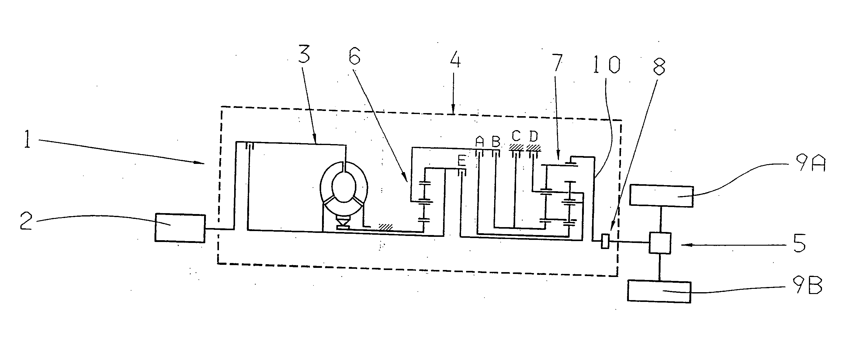
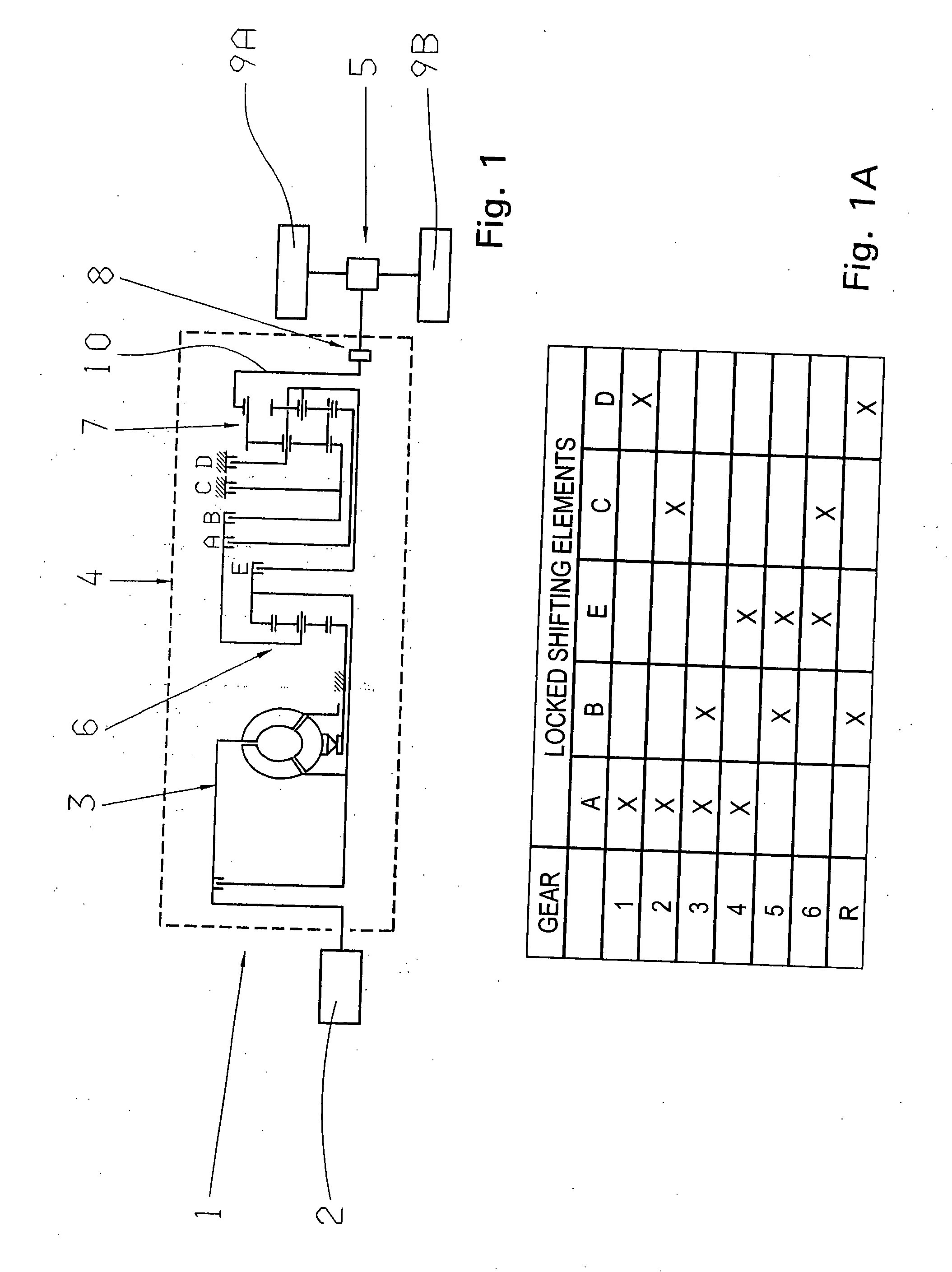
[0042]FIG. 1 shows schematically a drive train 1 of a motor vehicle, which comprises a drive motor 2 in the form of an internal combustion engine; a starting element 3, configured as a hydrodynamic torque converter; a transmission 4 and an output 5. The transmission 4 is, for example, an automatic power shift transmission, having a simple first planetary set 6 on the input side of the transmission and a second planetary set 7 on the output side of the transmission, designed as a Ravigneaux planetary wheel set. For the implementation of various speed ratios or gear ratios of the transmission 4, five shifting elements A through E are arranged between the two planetary sets 6 and 7, and are configured, in the known manner, as multiple disc clutches and multiple disc brakes. Depending on the actuation of the shifting elements A through E, a drive torque of the drive motor 2 can be passed at various speeds of the transmission 4 to the output 5. From the transmission scheme, it can be see...


PUM


Abstract

A vehicle transmission having shifting elements (A-E) and a parking brake for locking a drive train output and a method for controlling the transmission. Activation of the parking brake depends on a driver's control action. Deactivating the parking brake, when the vehicle is on a slope greater or lesser than a preset value and depending on the slope, a combination of shifting elements (A, D) or (B, D) frictionally slip, such that the output rotates against the strain on a parking brake locking element, caused by the slope, to partially eliminate this strain. Next, one of shifting elements (C, A or B) engages locking the output. The parking brake is then released and finally, the engaged shifting element (C or A or B) is disengaged in a regulated manner, such that the output can be driven according to the driver's control action.

Description

[0001] This application is a national stage completion of PCT / EP2005 / 007621 filed Jul. 13, 2005, which claims priority from German Application Serial No. 10 2004 043 416.6 filed Sep. 8, 2004.FIELD OF THE INVENTION [0002] The invention concerns a method for controlling a vehicle transmission with a parking brake for the positive locking of a drive of a drive train, as well as a vehicle transmission with a parking brake for the positive locking restraint of an output of a drive train. BACKGROUND OF THE INVENTION [0003] Vehicles with manual transmissions and the motor turned off can generally be secured from rolling away by way of a parking brake, and additionally by way of a gear, having with a high transmission ratio, being inserted into the transmission and locking an output of the drive train. In vehicles, the drive trains of which are configured with a hydrodynamic torque converter or a hydrodynamic clutch, this possibility does not apply since, with a turned off motor, a connecti...

Claims


Application Information

Patent Timeline
IPC IPC(8): B60T1/06B60W10/18F16H61/00
CPCF16H61/0059F16H61/686F16H63/483F16H2200/0052F16H2200/2007Y10T477/644F16H2200/2043F16H2200/2097F16H2312/02F16H2312/12F16H2200/2023
Inventor SCHIELE, PETERZIEMER, PETER
Owner ZF FRIEDRICHSHAFEN AG
Learn More