Extreme ultra violet light source device

a light source device and ultra violet technology, applied in the field of ultra violet (euv) light source devices, can solve the problems of high cost of euv collector mirrors, sputtered mirrors, damaged reflection surfaces, etc., and achieve the effect of high speed

Inactive Publication Date: 2008-02-14
GIGAPHOTON
View PDF27 Cites 53 Cited by
  • Summary
  • Abstract
  • Description
  • Claims
  • Application Information

AI Technical Summary

Benefits of technology

[0016] According to the present invention, since the magnetic field for trapping the charged particles emitted from the plasma is formed to have the substantially straight lines of magnetic flux in substantially parallel with the traveling direction of the target material in the track of the target material, even when the charged target material is injected into such a region, a change of the track due to the effect of the magnetic field can be suppressed. Therefore, the target material is stably supplied to the plasma generation point, and both the technology of supplying the target materials at a high speed and the technology of trapping the charged particles are managed.

Problems solved by technology

In the LPP EUV light source apparatus, the influence of fast ions and fast neutral particles emitted from plasma is problematic.
This is because the EUV collector mirror is located near the plasma and the reflecting surface of the mirror is sputtered and damaged by those particles.
Nevertheless, the EUV collector mirror is required to have the high surface flatness of about 0.2 nm (rms), for example, in order to maintain the high reflectance, and thus, the EUV collector mirror is very expensive.
However, in application of both the technology of charging and accelerating a droplet target (JP-P2003-297737A) and the technology of trapping charged particles by the effect of the magnetic field (U.S. Pat. No. 6,987,279B2), the following problem will occur.
Consequently, the stability of EUV light becomes lower and available EUV light is reduced.
Further, the operation cost and the maintenance cost of the EUV light source apparatus are increased due to reduction in utilization efficiency of the EUV light, and the performance of EUV exposure equipment is deteriorated due to lack of stability in luminance of the EUV light, and finally, the quality of semiconductor devices produced by the EUV exposure equipment will be unstable.

Method used


Image

  • Extreme ultra violet light source device
  • Extreme ultra violet light source device
  • Extreme ultra violet light source device

Examples


first embodiment

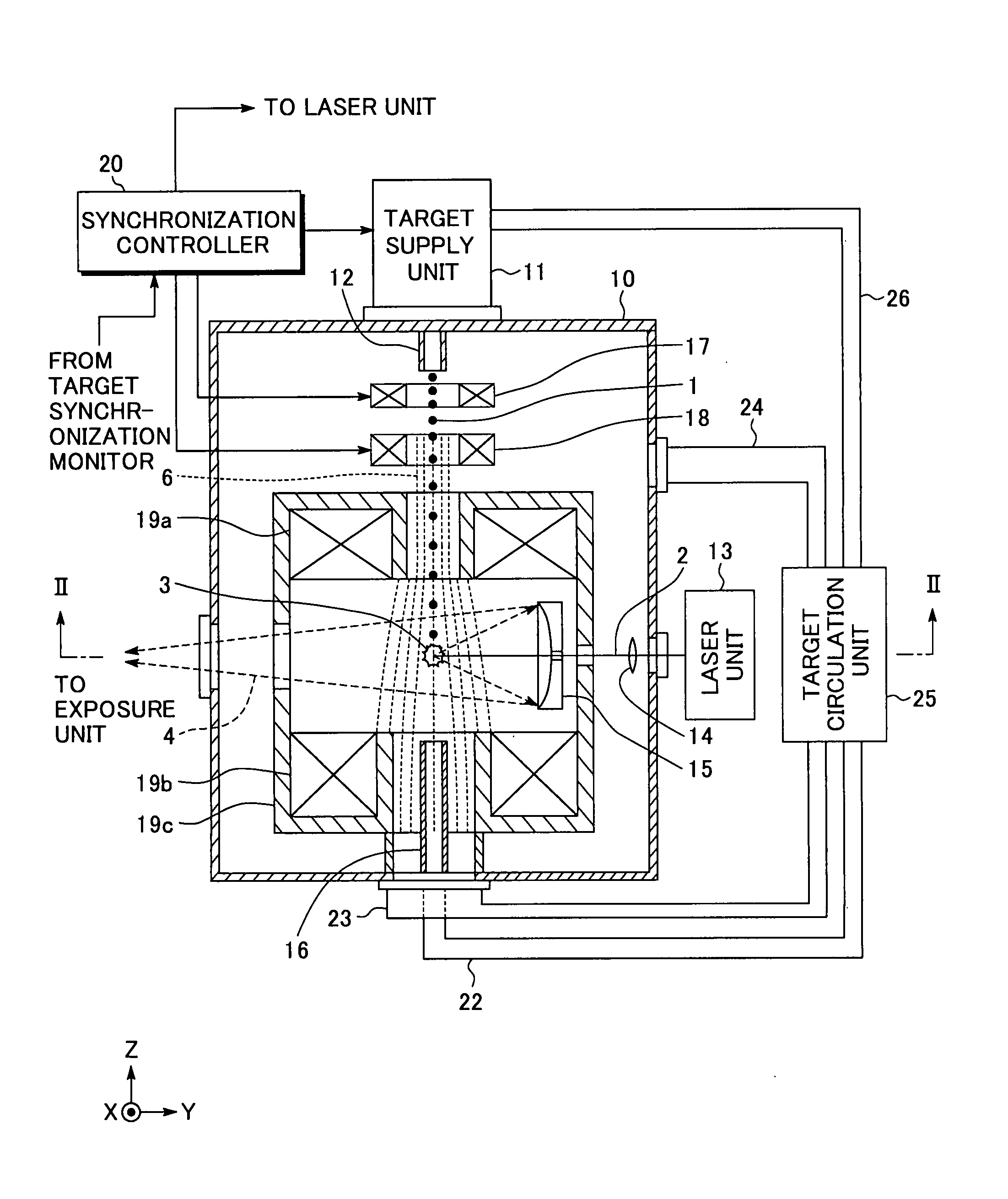
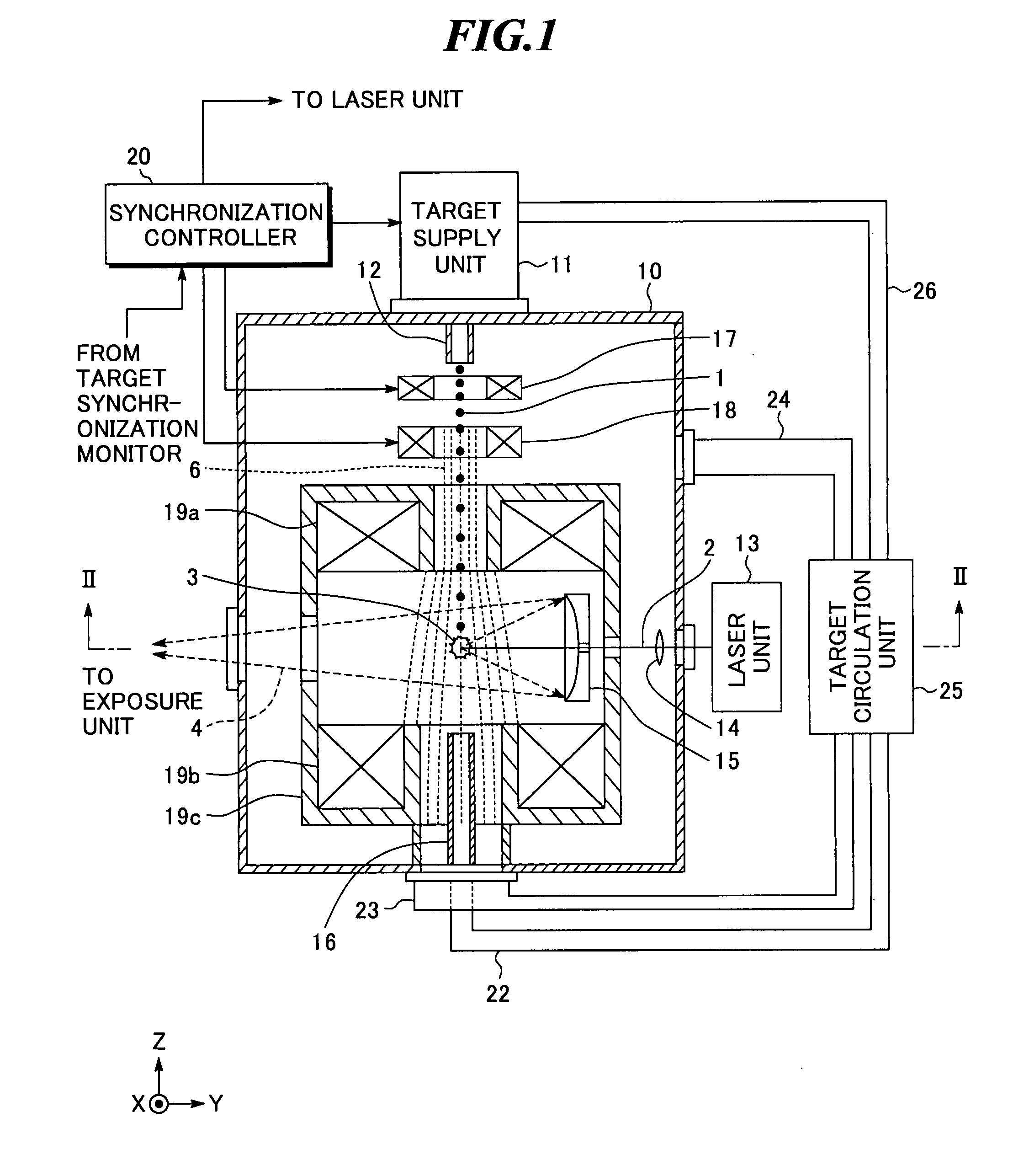
[0037]FIG. 1 shows a configuration of an extreme ultra violet (EUV) light source apparatus according to the present invention. Further, FIG. 2 is a sectional view along II-II shown in FIG. 1. The EUV light source apparatus according to the embodiment employs a laser produced plasma (LPP) system of generating EUV light by applying a laser beam to a target material to excite the target material.

[0038] As shown in FIGS. 1 and 2, the EUV light source apparatus includes a chamber 10 in which EUV light is generated, a target supply unit 11, a target nozzle 12, a laser unit 13, a collective lens 14, an EUV collector mirror 15, a target collection cylinder 16, an electric charge supply unit 17, an acceleration unit 18, electromagnets 19a and 19b and a yoke 19c, a synchronization controller 20, and a target monitor 21. The EUV light source apparatus may further include a target collection pipe 22, an ion exhaust tube 23, a target exhaust tube 24, a target circulation unit 25, and a target su...

second embodiment

[0084] Next, an extreme ultra violet light source apparatus according to the present invention will be explained with reference to FIG. 12.

[0085] The extreme ultra violet light source apparatus according to the embodiment is further provided with an auxiliary magnetic field forming unit 31 in addition to the extreme ultra violet light source apparatus shown in FIG. 1. The rest of the configuration is the same as that shown in FIG. 1.

[0086] Here, in the magnetic field formed by the electromagnets 19a and 19b, lines of magnetic flux are diverged as they are apart from the electromagnet 19a. Further, when the yoke 19c is provided to the electromagnets 19a and 19b, the lines of magnetic flux are more easily diverged. Accordingly, in the embodiment, the auxiliary magnetic field forming unit 31 is provided for making the lines of magnetic flux substantially straight in the broader region and in substantially parallel with the traveling direction of the target material 1. Thereby, change ...

third embodiment

[0088] Next, an extreme ultra violet light source apparatus according to the present invention will be explained with reference to FIG. 13.

[0089] The extreme ultra violet light source apparatus according to the embodiment is further provided with an auxiliary magnetic field forming unit 32 above the acceleration unit 18 in addition to the extreme ultra violet light source apparatus shown in FIG. 12.

[0090] Here, when charge is provided to the target material 1 by the electric charge supply unit 17, the material is immediately affected by the magnetic field. Accordingly, in the embodiment, the auxiliary magnetic field forming unit 32 is provided for broadening the region where the lines of magnetic flux are made substantially straight and in substantially parallel with the traveling direction of the target material 1. Thereby, change in the track of the charged target material 1 is more reliably suppressed. As the auxiliary magnetic field forming unit 32, an electromagnet, supercondu...


PUM


Abstract

An extreme ultra violet light source apparatus in which both a mechanism of supplying a droplet target to a laser application position at a high speed and a mechanism of trapping charged particles generated from plasma are managed without disturbing a track of the target. The apparatus includes: a target nozzle that injects a target material toward a plasma generation point; an electric charge supply unit that charges the injected target material; an acceleration unit that accelerates the charged target material; a laser oscillator that applies a laser beam to the target material at the plasma generation point to generate plasma; and electromagnets that form a magnetic field at the plasma generation point such that the magnetic field has substantially straight lines of magnetic flux in substantially parallel with a traveling direction of the target material in the track of the target material.

Description

BACKGROUND OF THE INVENTION [0001] 1. Field of the Invention [0002] The present invention relates to an extreme ultra violet (EUV) light source apparatus to be used as a light source of exposure equipment. [0003] 2. Description of a Related Art [0004] Recent years, as semiconductor processes become finer, photolithography has been making rapid progress to finer fabrication. In the next generation, microfabrication of 100 nm to 70 nm, further, microfabrication of 50 nm or less will be required. Accordingly, in order to fulfill the requirement for microfabrication of 50 nm or less, for example, exposure equipment is expected to be developed by combining an EUV light source generating EUV light with a wavelength of about 13 nm and reduced projection reflective optics. [0005] As the EUV light source, there are three kinds of light sources, which include an LPP (laser produced plasma) light source using plasma generated by applying a laser beam to a target (hereinafter, also referred to ...

Claims


Application Information

Patent Timeline
Patent Type & Authority Applications(United States)
IPC IPC(8): H05G2/00
CPCH05G2/005H05G2/001
Inventor KOMORI, HIROSHIENDO, AKIRAMIZOGUCHI, HAKARU
Owner GIGAPHOTON
Why Eureka
Try Eureka