[0005]An
advantage of the present invention is to offer a solution to the above-noted problem of the conventional techniques by providing a simply-configured detection apparatus for optically determining a property of a biological material. The present invention advantageously provides a detection apparatus for optically determining a biological material property which measurement of a two-dimensional distribution of a material property using an apparatus of simple configuration.
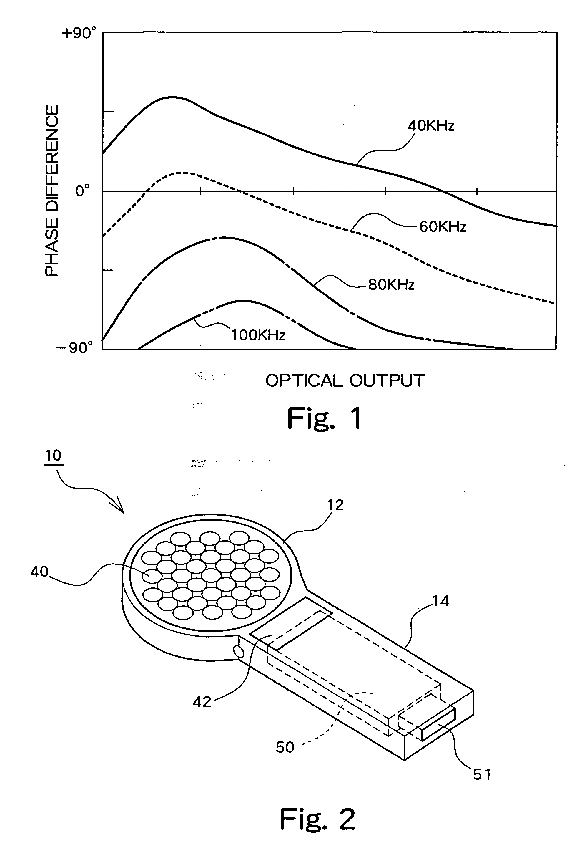
[0006]The present invention is based on the discovery that, when a periodic optical output is applied to a living body by driving a light emitting element, and changes in the reflected light are then observed by capturing the changes using a light receiving element, generation of a
phase difference between the periodic input
signal which drives the light emitting element and the periodic output
signal extracted from the light receiving element can be confirmed. FIG. 1 shows example observation results obtained by applying periodic light emitted from an LED (
light emission diode) to fat tissue (which is one type of
biological tissue), detecting the reflected light by means of a
photodiode, and observing the
phase difference between the input
signal supplied to the LED and the output signal from the
photodiode. In FIG. 1, optical output from the LED is given on the
horizontal axis, while phase difference between the input signal and the output signal is given on the
vertical axis. The varied parameter in FIG. 1 is the frequency of the input signal. As shown in FIG. 1, when monitoring the output signals from the
photodiode obtained by applying periodic lights to a biological tissue, phase differences which depend on the optical output and the input frequency are detected. Further, it has also been confirmed that the magnitude of phase difference is varied by different biological tissues. Accordingly, it can be understood that the phase difference denotes a biological material property with respect to light.
[0007]The present inventor previously devised a phase shift method, which is a method for accurately determining a phase difference between an input signal and an output signal (refer to Japanese Patent Laid-Open Publication No. Hei 9-145691). In the present invention, the phase shift method is applied to the measurement of the phase difference generated between the input signal and the output signal when light is introduced into a living body, so as to accurately and quantitatively determine a property of a biological material (a biological material property) with respect to light.
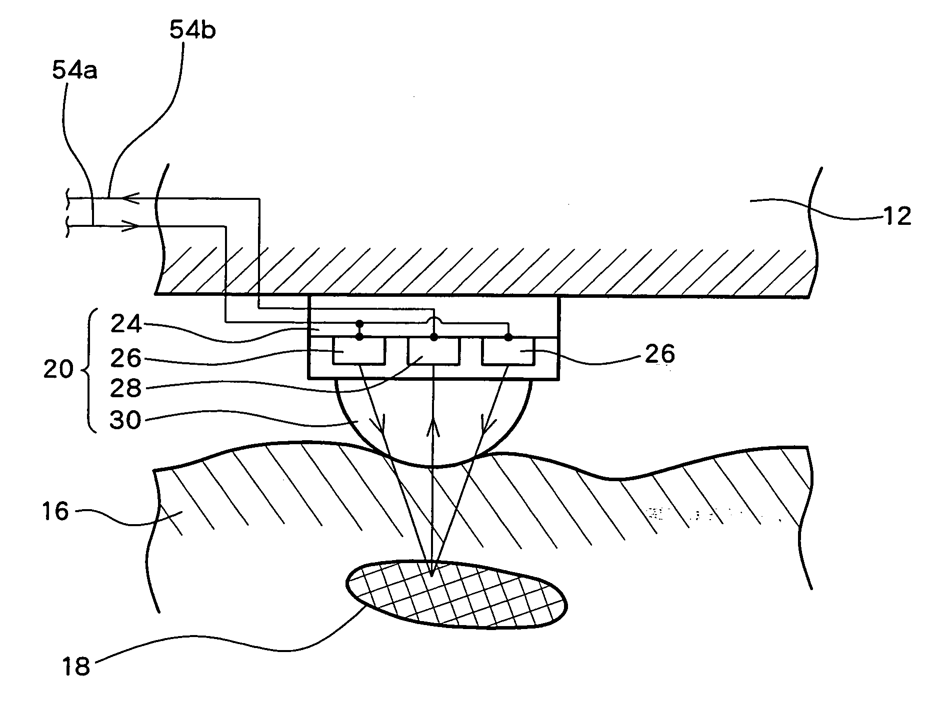
[0008]In consideration of the above-noted findings, a detection apparatus for optically determining a biological material property according to the present invention comprises a probe base and a probe supported on the probe base. The probe includes a light emitting element for applying light to a living body and a light receiving element for receiving light from the living body. The detection apparatus further comprises an
amplifier having an input terminal connected to a signal output terminal of the light receiving element, and a
phase compensation circuit provided between an output terminal of the
amplifier and a signal input terminal of the light emitting element for changing the
signal frequency so as to cause any phase difference between an input waveform into the light emitting element and an output waveform from the light receiving element to become zero. The detection apparatus further comprises a
frequency difference detector which measures a frequency of a self-induced oscillation generated when the phase difference is made to become zero by means of a
feedback loop formed by the probe, the
amplifier, and the
phase compensation circuit, and detects a difference between a frequency obtained when receiving light from the living body by applying light from the probe to the living body and a frequency obtained when such light is not applied to the living body. The detection apparatus further comprises output means for outputting the detected
frequency difference as a material property of the living body.
[0009]According to another aspect, a detection apparatus for optically determining a biological material property according to the present invention comprises a probe base and a plurality of probes two-dimensionally arranged and supported on the probe base. Each probe includes a light emitting element for applying light to a living body and a light receiving element for receiving light from the living body. The detection apparatus further comprises a material property
calculator provided so as to be connectable between a signal input terminal of the light receiving element and a signal output terminal of the light emitting element in each probe for calculating a material property of the living body, a switch circuit for successively switching connection of the material property
calculator to the respective probes, and a display unit for providing a two-dimensional display of the material properties calculated for the respective probes. The material property
calculator comprises an amplifier having an input terminal connected to a signal output terminal of the light receiving element, and a
phase compensation circuit provided between an output terminal of the amplifier and a signal input terminal of the light emitting element for changing the
signal frequency so as to cause any phase difference between an input waveform into the light emitting element and an output waveform from the light receiving element to become zero. The material property calculator further comprises a
frequency difference detector which measures a frequency of a self-induced oscillation generated when the phase difference is made to become zero by means of a
feedback loop formed by the probe, the amplifier, and the phase compensation circuit, and detects a difference between a frequency obtained when receiving light from the living body by applying light from the probe to the living body and a frequency obtained when such light is not applied to the living body. The detection apparatus determines a material property of the living body based on a two-dimensional distribution of the frequency differences.
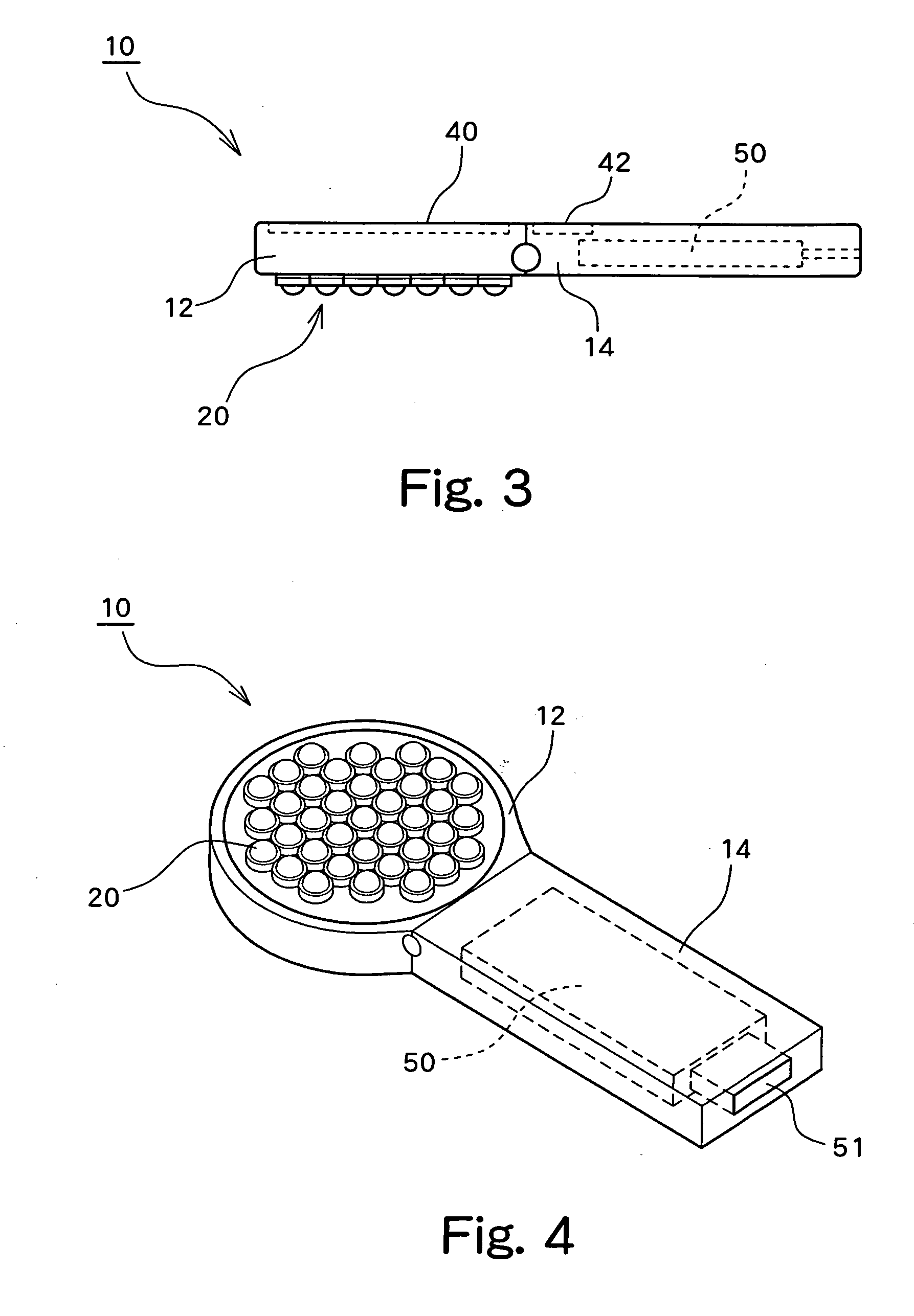
[0010]The display unit is preferably provided on the probe base on a rear surface located opposite from the surface on which the probes are arranged.

