
Transmission apparatus

Inactive Publication Date: 2008-02-14
FUJITSU LTD
View PDF7 Cites 34 Cited by
  • Summary
  • Abstract
  • Description
  • Claims
  • Application Information

AI Technical Summary

Benefits of technology

[0011]Here, the SONET / SDH frame format means a frame format defined by SONET which is an ANSI standard or SDH of the ITU Recommendation. According to the transmission apparatus according to the invention, packet format data is converted to variable length frame format data first and is then converted to SONET / SDH frame format data. Therefore, according to the invention, transmission loss is suppressed compared to the configuration whereby packet format data is subdivided into fixed length frames.
[0015]When a fault occurs in a receiving side line interface, it is possible to prevent data omissions and suppress degradation of transmission quality by stopping data conversion at a transmitting side line interface and buffering the data.
[0017]The circuit switching section fixes the distribution of logical data paths and the transmitting side line interface selects a logical data path through which data is allowed to pass, and in this way the switching setting at the circuit switching section is not dynamically changed, and it is thereby possible to speed up data transmission.
[0025]As described above, the invention realizes a transmission apparatus that suppresses transmission loss.

Problems solved by technology

However, packet switching cannot avoid fluctuations in a transmission time and data buffering is required to absorb these fluctuations.
Therefore, it is difficult to realize a large-capacity transmission apparatus because the problem of delays due to buffering becomes serious with such a transmission apparatus.
However, the scheme described in National Publication of International Patent Application No. 2004-519123 subdivides packet data into 52-byte fixed length frames as defined in ATM and then performs mapping, and loss is thereby produced due to overhead generated every 52-byte fixed length frame and insertion of data to fill the blanks of fixed length frames, which suppresses transmission bandwidths.

Method used


Image

  • Transmission apparatus
  • Transmission apparatus
  • Transmission apparatus

Examples


Embodiment Construction

[0042]With reference now to the attached drawings, an embodiment of the transmission apparatus according to the invention will be explained below.

[Overall Configuration of Transmission Apparatus]

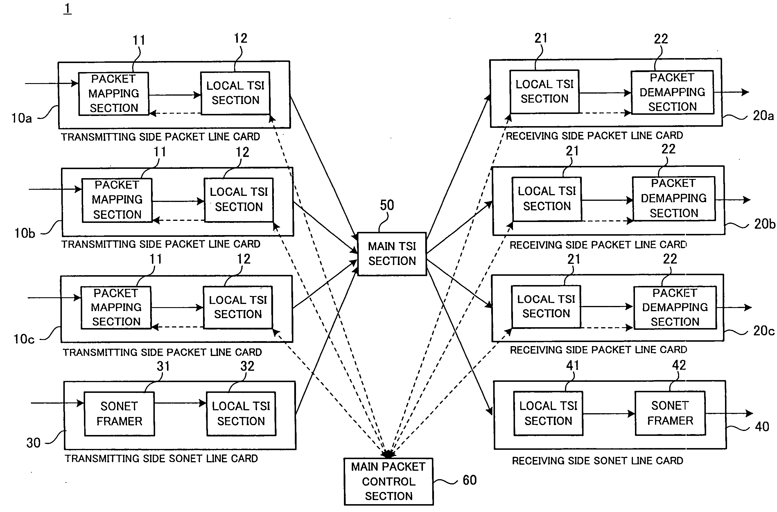
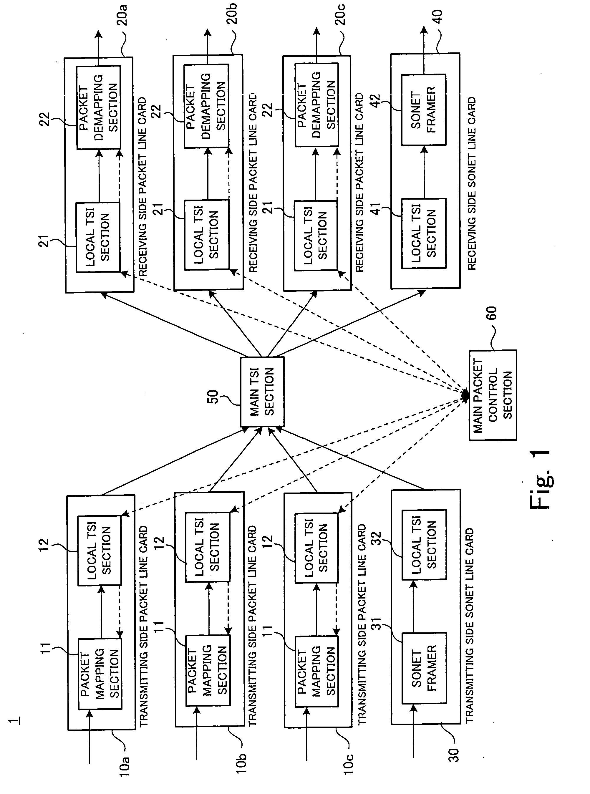
[0043]FIG. 1 is a block diagram showing an embodiment of the transmission apparatus according to the invention. Of SONET and SDH, SONET will be explained as a representative in this embodiment.

[0044]A transmission apparatus 1 shown in FIG. 1 is a transmission apparatus which accommodates an IP packet network which is an asynchronous network and a SONET network and provided with transmitting side packet line cards (Packet Line Cards) 10 (10a, 10b, 10c), receiving side packet line cards (Packet Line Cards) 20 (20a, 20b, 20c), a transmitting side SONET line card (Line Card) 30, a receiving side SONET line card (Line Card) 40, a main time slot interchange 50 (Main Time Slot Interchange; hereinafter abbreviated as “main TSI section 50”) which performs circuit switching and a main packet control s...


PUM


Abstract

The present invention provides a transmission apparatus including transmitting side line interfaces which convert packet format data sent from an asynchronous network to a SONET / SDH frame format and then transmit the data, multiple receiving side line interfaces which receive the SONET / SDH frame format data and convert the data to packet format data and a circuit switching section which performs circuit switching. The transmitting side line interfaces include a variable length frame mapping section which converts the packet format data to variable length frame format data and a time division multiplexing mapping section which converts the variable length frame format data to the SONET / SDH frame format data. The receiving side line interfaces include a variable length frame demapping section which reconverts the SONET / SDH frame format data to variable length frame format data.

Description

BACKGROUND OF THE INVENTION[0001]1. Field of the Invention[0002]The present invention relates to a transmission apparatus, and more particularly, to a transmission apparatus which accommodates an asynchronous network and a SONET / SDH network.[0003]2. Description of the Related Art[0004]As a conventional transmission network, a synchronous network under a SONET / SDH scheme specified in SONET (Synchronous Optical Network) which is an ANSI (American National Standards Institute) standard or in SDH (Synchronous Digital Hierarchy) of ITU Recommendation is widely used. Data transmission over this SONET / SDH network secures a congestion-free fixed bandwidth. On the other hand, with the widespread use of the Internet in recent years, there is a growing trend to convert telephone voice data to IP (Internet Protocol) packets and transmit the data asynchronously through a router, that is, “IP implementation” and there is a growing demand for this packet transmission over a transmission network. T...

Claims


Application Information

Patent Timeline
IPC IPC(8): H04J3/16H04J3/00H04L49/111
CPCH04J3/1611H04L49/602H04L49/552H04J3/1629
Inventor ASANO, HIROYUKI
Owner FUJITSU LTD
Learn More