Image display system, image display device of image display system, mobile terminal device, connection establishment method of image display system

Active Publication Date: 2008-02-14
SEIKO EPSON CORP
View PDF3 Cites 55 Cited by
  • Summary
  • Abstract
  • Description
  • Claims
  • Application Information

AI Technical Summary

Benefits of technology

[0070]Therefore, since it is possible to prevent the connection impossibility due to mismatch between the image display device and the connection information, it is possible to improve the reliability of the connection.
[0071]Since the step of taking the image including the connection information code and the step of analyzing and acquiring the connection information from the imaged connection information code in the mobile terminal device are included, it is pos

Problems solved by technology

In addition, it is difficult to perform the connection configuration without a knowledge of a network configuration although the connection information is previously examined.
Since the mobile terminal device 50 needs to access to the ID information unit in order to read the connection information from the ID information unit, the mobile terminal device 50 moves to a place where t

Method used


Image

  • Image display system, image display device of image display system, mobile terminal device, connection establishment method of image display system
  • Image display system, image display device of image display system, mobile terminal device, connection establishment method of image display system
  • Image display system, image display device of image display system, mobile terminal device, connection establishment method of image display system

Examples


embodiment 1

Outline of First Image Display System

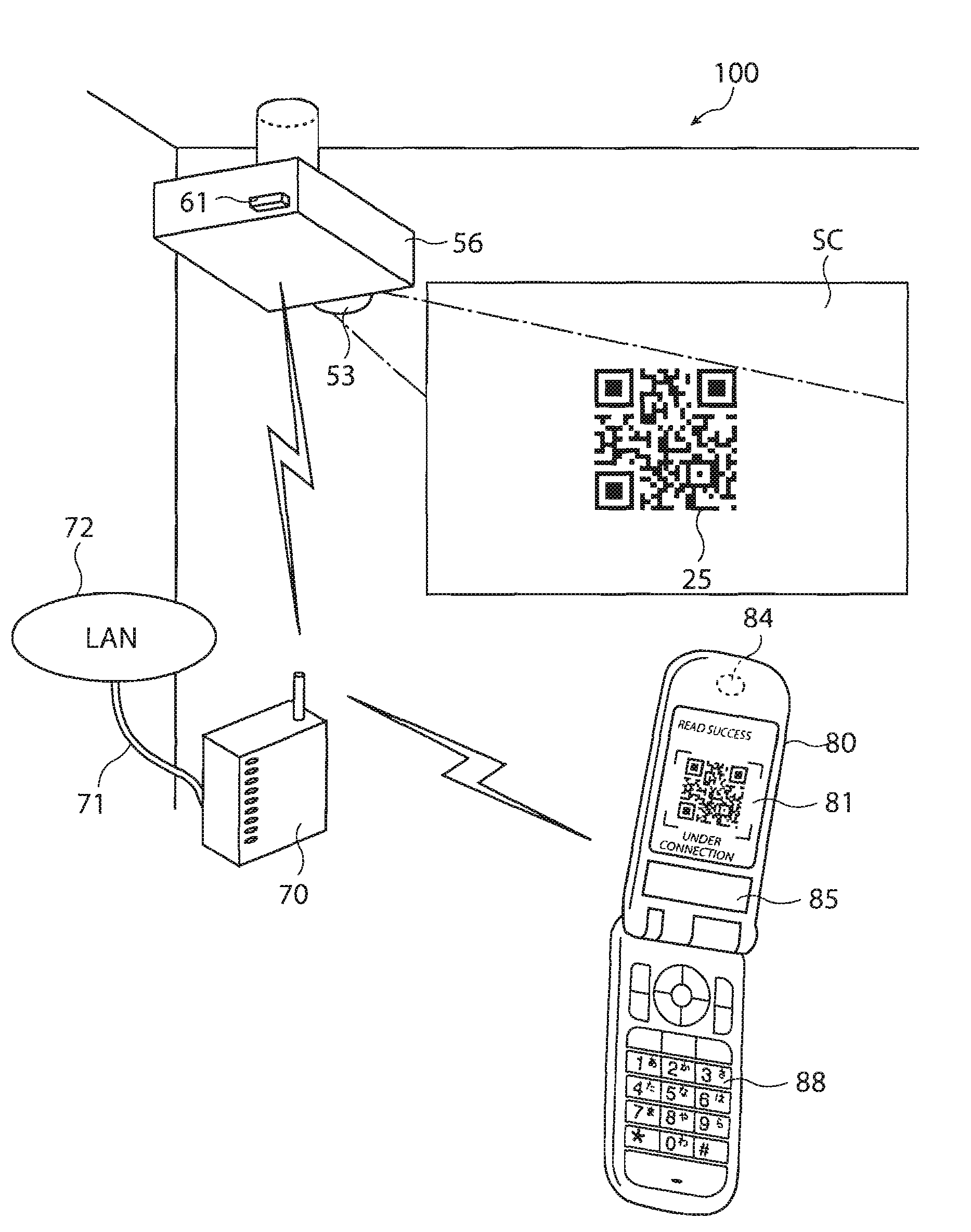
[0081]FIG. 1 is a schematic view showing the configuration of an image display system 100 according to Embodiment 1. Now, the outline of the image display system 100 will be described using FIG. 1.

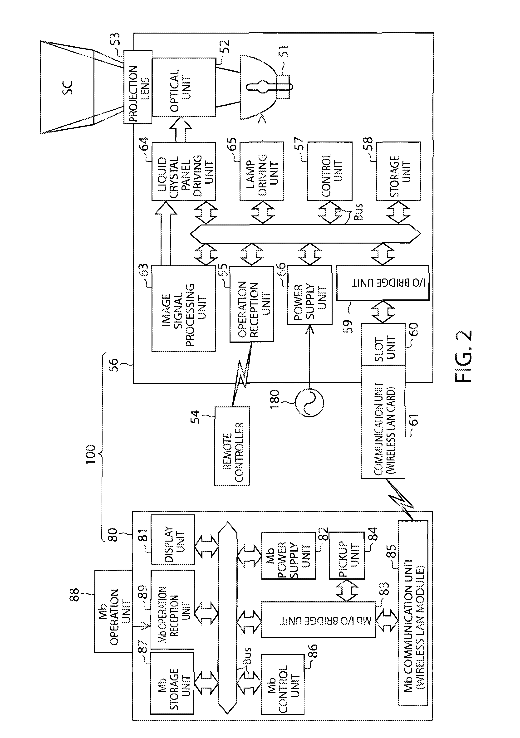
[0082]The image display system 100 includes a projector 56 serving as an image display device and a mobile telephone 80 serving as a mobile terminal device.

[0083]The projector 56 hangs from the ceiling of a conference room and projects an image onto a screen SC provided on a wall.

[0084]The projector 56 includes a projection lens 53 serving as a display unit for projecting an image and a communication unit 61 which is a wireless terminal device corresponding to a wireless LAN.

[0085]The projector 56 expands and projects an image including a connection information code 25 which is a two-dimensional code obtained by encoding connection information for connecting to the projector in the wireless LAN. This operation is performed by connecting to an external m...

embodiment 2

Outline of Second Image Display System

[0179]FIG. 5 is a schematic view showing an image display system 200 according to Embodiment 2 of the invention. Now, the outline of the image display system 200 will be described with respect to FIGS. 5 and 1. The image display system 200 includes a projector 150 serving as an image display device and a mobile telephone 180 as a mobile terminal device.

[0180]While the connection between the projector 56 and the mobile telephone 80 is established by the wireless LAN as a predetermined network in the image system 100 (FIG. 1) of Embodiment 1, the connection between the projector 150 and the mobile telephone 180 is established by a wireless USB as a predetermined network in the image system 200. The wireless USB is a wireless communication technology based on the certified wireless USB obtained by converting a universal serial bus (USB), which is the standard of the transmission channel using a wired cable, into a wireless USB.

[0181]The image syste...

modified embodiment 1

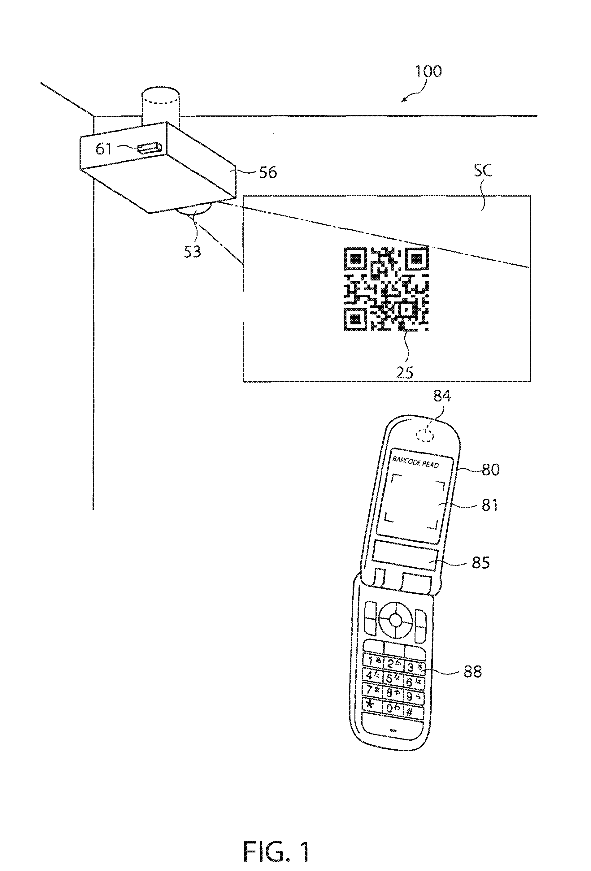
[0251]This embodiment will be described with reference to FIG. 3. Although, in Embodiment 1, the operation for starting the connection with the external projector is performed by selecting a hierarchy menu from the “connection with other device” operation menu of the mobile telephone 80, the invention is not limited to this operation.

[0252]For example, a barcode read program which is basically mounted in the mobile telephone may start up. In particular, the operation is executed by selecting the “barcode read” from the operation menu of the mobile telephone 80. Accordingly, the connection information code imaging screen in a step S12 is displayed on the display unit 81 of the mobile telephone 80 to become a state that the connection information code can be taken the image.

[0253]In this configuration, when the extracted two-dimensional code or the three-dimensional code is the connection information code, the barcode read program includes a subroutine for starting up the connection e...


PUM


Abstract

An image display system is disclosed. The image display system includes an image display device forming an image and a mobile terminal device supplying image information to the image display device over a predetermined network, wherein the image display device includes: a storage unit which stores connection information for connecting to the image display device in the predetermined network; an encoding unit which encodes connection information code including the connection information; and a display unit which displays the connection information code or an image including the connection information code, and wherein the mobile terminal device includes: a code acquiring unit which acquires the connection information code from the displayed connection information code or the image including the connection information code; a code analysis unit which analyzes the connection information from the acquired connection information code; and a network connection establishment unit which establishes network connection with the image display device on the basis of the analyzed connection information.

Description

[0001]The entire disclosure of Japanese Patent Application No. 2006-140020, filed May 19, 2006 is expressly incorporated by reference herein.BACKGROUND[0002]1. Technical Field[0003]The present invention relates to an image display device displaying an image, an image display system including a mobile terminal device supplying image information to the image display device, and a connection establishment method of the image display system.[0004]2. Related Art[0005]As personal computers (hereinafter, referred to as PCs), projectors and large-sized television sets come into wide use, a conference using an image expanded by a variety of devices has been frequently held. In such a conference, a projector or a large-sized television set provided in a conference room of an enterprise is mainly used.[0006]In particular, in a conference in which many people participate, since an operation for connecting a cable to different PCs is needed whenever a person who gives a presentation is changed o...

Claims


Application Information

Patent Timeline
IPC IPC(8): H04Q7/24H04M3/00H04W8/00H04W28/00H04W84/12H04W88/02
CPCH04M1/2755H04M3/56H04M2250/02H04L67/04H04M2250/54H04L67/36H04M2250/06H04L67/75
Inventor ICHIEDA, HIROYUKI
Owner SEIKO EPSON CORP
Why Eureka
Try Eureka