
Facilitating oilfield development with downhole fluid analysis

a technology of fluid analysis and oilfield development, applied in the field of oil and gas wells, can solve the problems of limited use of coarsened geological models, low confidence in these models, and insufficient availability of known reservoir simulation models. , to achieve the effect of improving exploration and field developmen

Inactive Publication Date: 2008-02-14
SCHLUMBERGER TECH CORP
View PDF2 Cites 97 Cited by
  • Summary
  • Abstract
  • Description
  • Claims
  • Application Information

AI Technical Summary

Benefits of technology

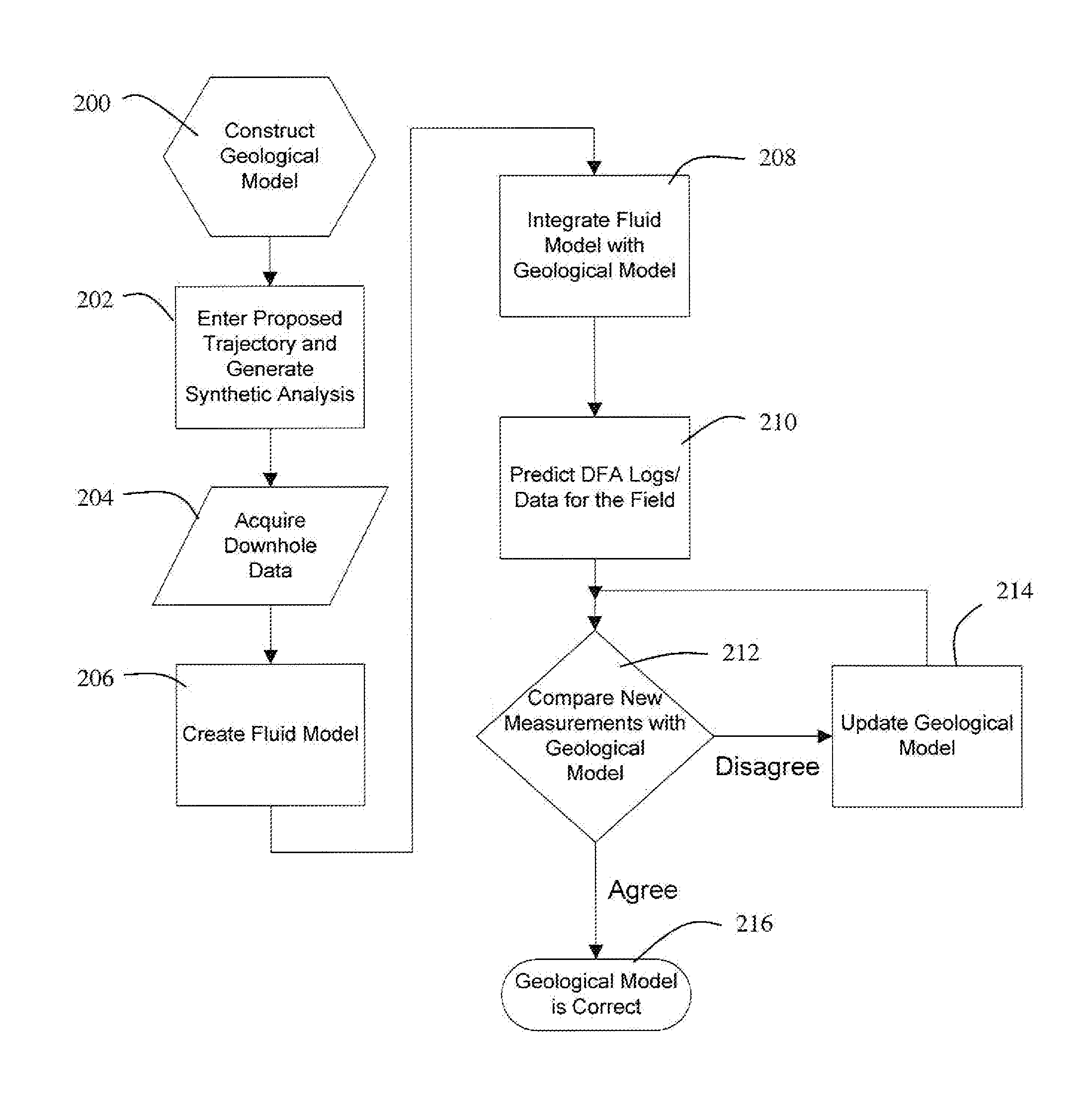
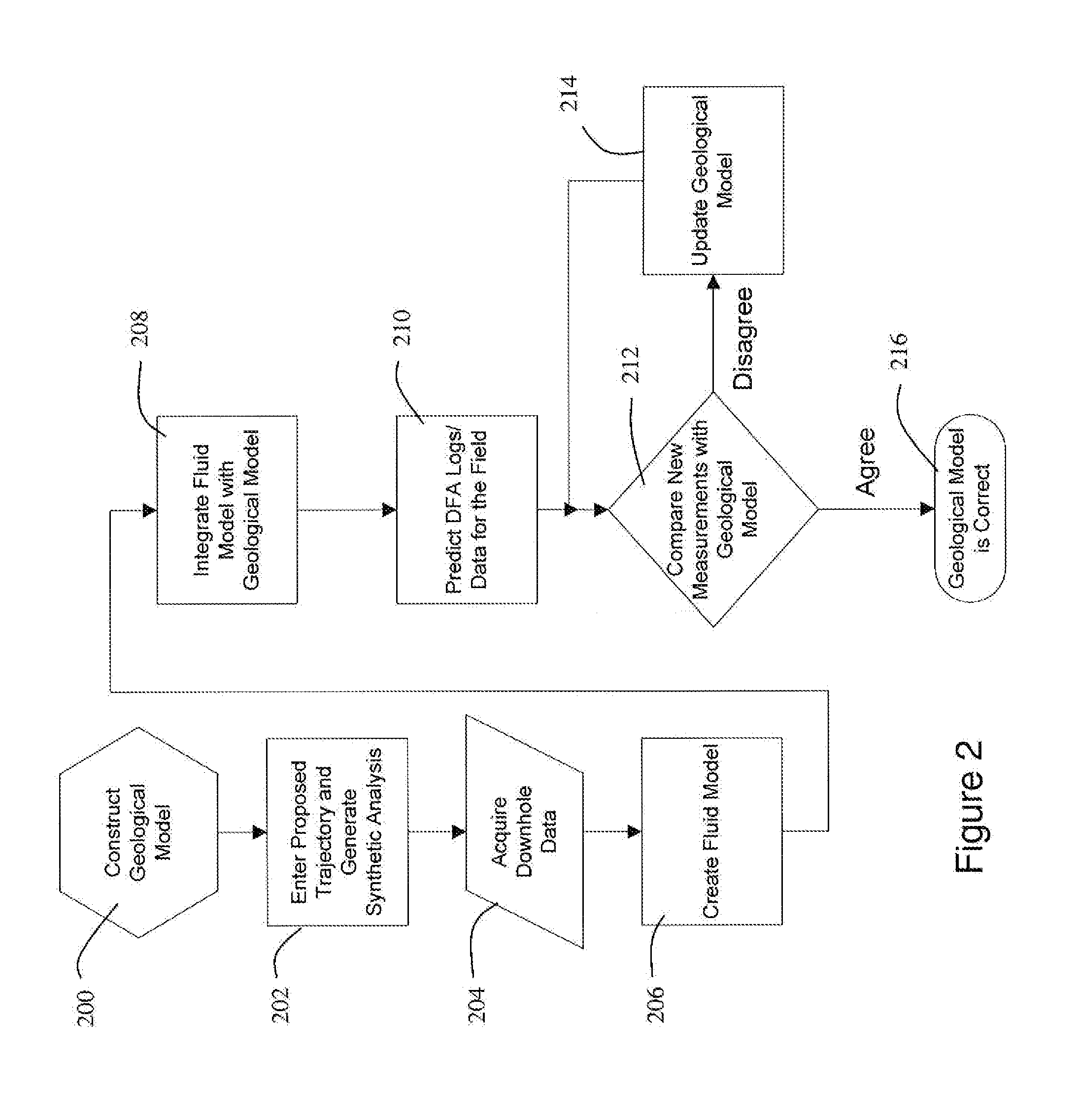
[0009] An object of at least one embodiment of the invention is to help verify a geological model, including identification and location of hydraulically isolated regions. Generally, the geological model is the most detailed representation of the reservoir before the field development stage. The geological model may be directly integrated with a calibrated fluids model, eliminating the need for history matching and forecasting stages of dynamic reservoir simulation during exploration, when production data is not yet available. Further, the integrated model can be used to generate synthetic DFA logs along the trajectory of a proposed borehole. This integrated geological model is updated with the newly acquired data such as (but not limited to) LWD logs, wireline formation evaluation and formation testing and sampling data. The synthetic DFA logs are also updated after measuring the actual formation pressure and temperature prior to sampling in order to reflect the effects of density variation in the absorption spectrum, and other fluid properties. During sampling, the synthetic logs are contrasted with the real measurements to assist with reservoir description, e.g., by verifying accuracy and prompting update. Agreement between the integrated geological model and real measurements may be interpreted as verification of the geological model. Disagreement may be indicative of inaccuracy in the geological model, e.g., because of the existence of previously unknown hydraulically isolated regions, among other things.
[0010] When production data becomes available, the calibrated fluids model may help optimize the process of history matching and production forecast with dynamic reservoir simulation.
[0011] Another advantage of at least one embodiment of the invention is improved exploration and field development. The measured fluid properties are used to create a model that captures the variations of fluid properties throughout the reservoir. Consequently, the model helps to discern whether variations observed in the fluids are due to natural segregation of certain components in the hydrocarbons or to geological features that prevent the fluids from mixing, e.g., reservoir compartment(s). The fluid model can also be used in dynamic reservoir simulation to predict the evolution of the reservoir under different production scenarios.

Problems solved by technology

One impediment to efficient development of oil and gas fields is reservoir compartmentalization.
However, prior to the field development stage, the uncertainty in these models is relatively high.
Consequently, combining the geological model and the fluids model in a reservoir simulation model yields a coarsened representation of the geological model with limited use, e.g., history matching and production forecasting.
Because of the limitations discussed above, known reservoir simulation models are not always available early enough, and with sufficient accuracy, to permit efficient field development.
This is a problem because relatively greater risk exists in the field development stage in comparison with the exploration stage.
If a mistake is made because of model inaccuracy, a costly workover operation and delayed production may result.
The risks are particularly high in the case of offshore development because of higher development and operating costs.

Method used


Image

  • Facilitating oilfield development with downhole fluid analysis
  • Facilitating oilfield development with downhole fluid analysis
  • Facilitating oilfield development with downhole fluid analysis

Examples


Embodiment Construction

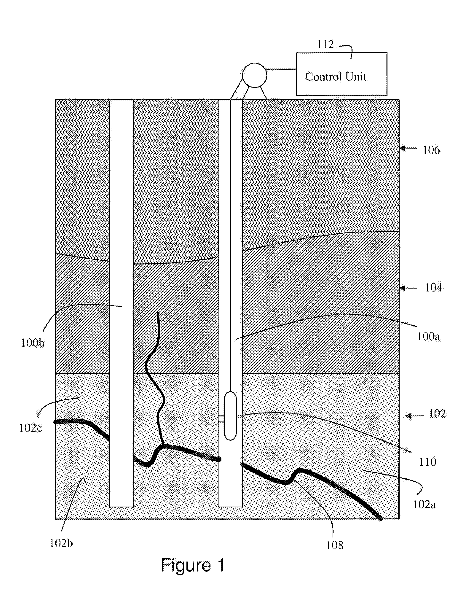
[0016]FIG. 1 illustrates boreholes (100a, 100b) drilled in a hydrocarbon field. The formation surrounding the borehole includes a hydraulically permeable layer (102) below an impermeable layer (104), and various other layers which make up the overburden (106) (not shown to scale in FIG. 1). Natural features such as a relatively thin impermeable layer (108) hydraulically isolates regions (102a, 102b, 102c) of the permeable layer, e.g., vertically, horizontally or both, such that the field is actually an aggregation of relatively small reservoirs. It will be appreciated that a well configured for recovery from only one of the hydraulically isolated reservoir will not recover fluid from another isolated reservoir.

[0017] A fluid analysis tool (110) is utilized to test fluid from the formation adjacent to the borehole (100a) in order to help identify locations of hydraulically isolated regions and other features. Differences in pressure and fluid properties generally indicate lack of hy...


PUM


Abstract

Formation fluid data based on measurements taken downhole under natural conditions is utilized to help identify reservoir compartments. A geological model of the reservoir including expected pressure and temperature conditions is integrated with a predicted fluid model fitted to measured composition and PVT data on reservoir fluid samples or representative analog. Synthetic downhole fluid analysis (DFA) logs created from the predictive fluid model can be displayed along the proposed borehole trajectory by geological modeling software prior to data acquisition. During a downhole fluid sampling operation, actual measurements can be displayed next to the predicted logs. If agreement exists between the predicted and measured fluid samples, the geologic and fluid models are validated. However, if there is a discrepancy between the predicted and measured fluid samples, the geological model and the fluid model need to be re-analyzed, e.g., to identify reservoir fluid compartments. A quantitative comparative analysis of the sampled fluids can be performed against other samples in the same borehole or in different boreholes in the field or region to calculate the statistical similarity of the fluids, and thus the possible connectivity between two or more reservoir regions.

Description

CROSS-REFERENCE TO RELATED APPLICATIONS [0001] A claim of priority is made to United States Provisional Patent Application 60 / 836,548, titled DOWNHOLE FLUID ANALYSIS WORKFLOW FOR OILFIELD DEVELOPMENT, filed Aug. 9, 2006, which is incorporated by reference.FIELD OF THE INVENTION [0002] This invention is generally related to oil and gas wells, and more particularly to in situ analysis of formation fluid in a hydrocarbon reservoir to generate a fluid model which is integrated with a geological model to help identify reservoir features that are relevant to borehole completion and reservoir development. BACKGROUND OF THE INVENTION [0003] One impediment to efficient development of oil and gas fields is reservoir compartmentalization. Reservoir compartmentalization is the natural occurrence of hydraulically isolated pockets within a single field. In order to produce an oil reservoir in an efficient manner it is necessary to know the structure of the field and the level of compartmentalizat...

Claims


Application Information

Patent Timeline
IPC IPC(8): G01V9/00G06F19/00G06G7/48
CPCE21B49/088E21B49/00
Inventor BETANCOURT, SORAYA S.MULLINS, OLIVER C.GAIZUTIS, RIMASXIAN, CHENGGANGKAUFMAN, PETERDUBOST, FRANCOISVENKATARAMANAN, LALITHA
Owner SCHLUMBERGER TECH CORP
Learn More