
Non-invasive determination of cardiac output, gas exchange and arterial blood gas concentration

a blood gas concentration and non-invasive technology, applied in the field of blood gas monitoring, can solve the problems of increased cardiac stress on patients, lung injury, and no percutaneous oxygenator is able to fully provide the necessary oxygenation

Inactive Publication Date: 2008-02-21
GENERAL ELECTRIC CO
View PDF19 Cites 29 Cited by
  • Summary
  • Abstract
  • Description
  • Claims
  • Application Information

AI Technical Summary

Benefits of technology

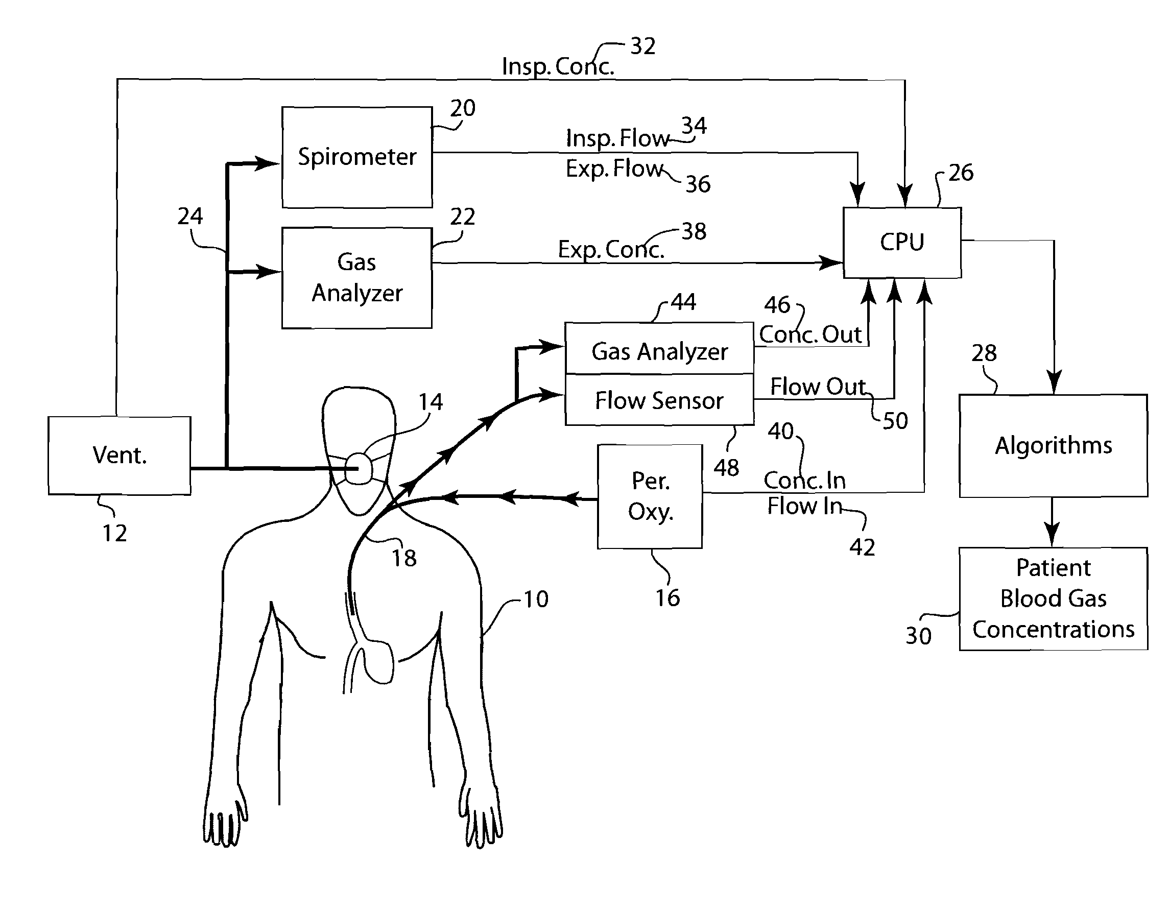
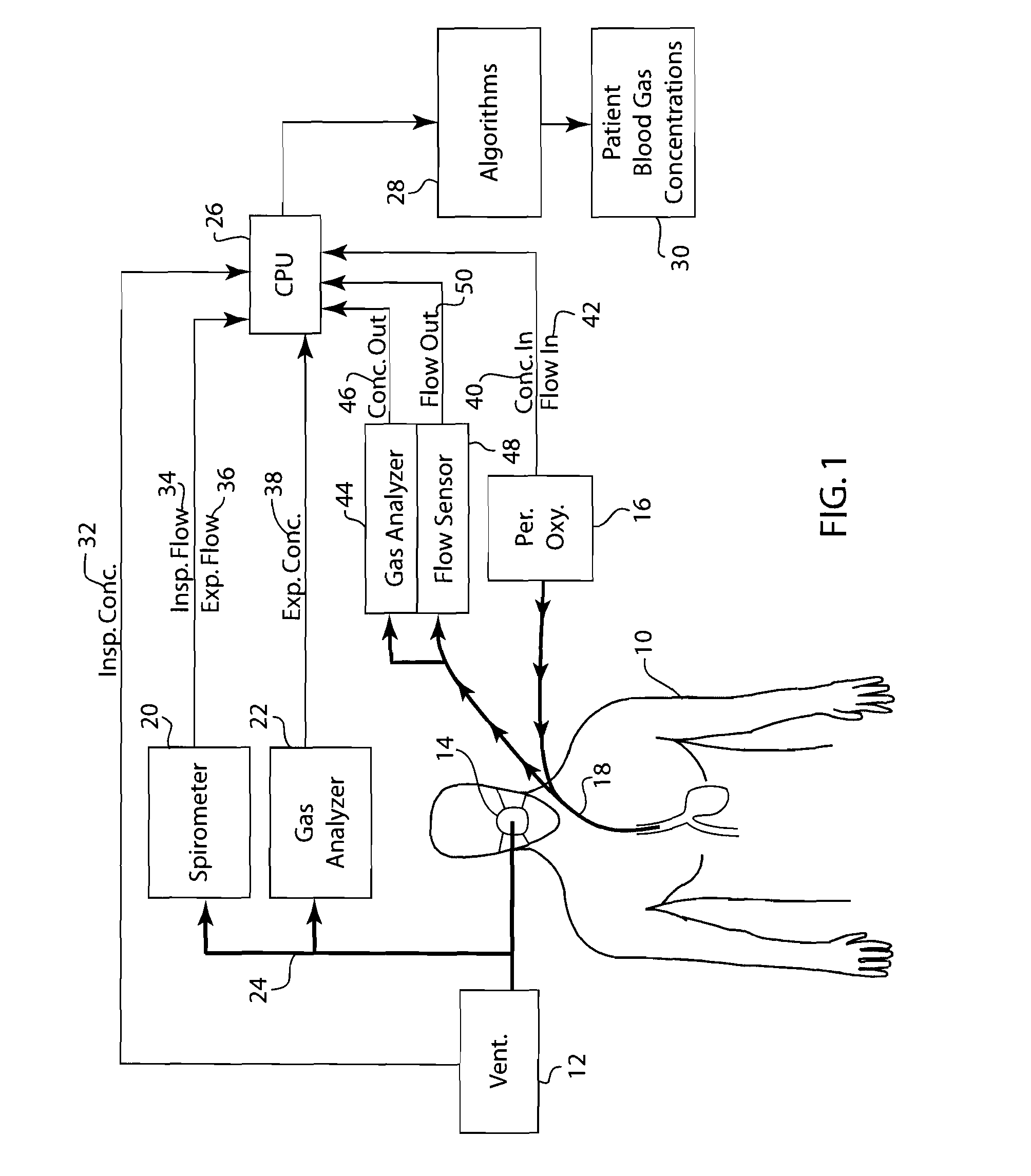
[0007]An embodiment of the present invention is a system that comprises exchange catheter gas composition data, such as the composition and flow rates in and out of a percutaneous oxygenator to determine patient venous blood gas concentration resulting in continuous computation of patient arterial blood gas concentration.

Problems solved by technology

While improvements to this design have been made, to date, no percutaneous oxygenator is able to fully provide the necessary oxygenation required.
This is desirable due to the fact that aggressive ventilatory treatment may cause lung injury or increase the cardiac stresses on the patient.
However, patients receiving mechanical ventilatory support often have compromised gas exchange in their lungs.
A patient receiving supplemental percutaneous oxygenator support often results in the erroneous prediction or estimation of the patient's blood gas concentration due to mismatched blood-gas exchange and compromised gas diffusion across the alveoli.
Solutions to this problem have been invasive and time-consuming.
While systems have been developed to automatically sample and analyze the patient's blood gas concentration, such as that disclosed in U.S. Pat. No. 4,516,580 to Polanyi, these systems require the invasive arterial insertion of a costly multi-parameter, multi-sensor transducer.
Despite improvements, all of the aforementioned systems are limited in their ability to continuously monitor a patient's blood gas concentration.
This inherently reduces the sampling rate of the patient's blood and additional time is required to compute the blood gas concentration.
These delays produce a lag time that can inaccurately display the patient's blood gas concentration.

Method used


Image

  • Non-invasive determination of cardiac output, gas exchange and arterial blood gas concentration
  • Non-invasive determination of cardiac output, gas exchange and arterial blood gas concentration
  • Non-invasive determination of cardiac output, gas exchange and arterial blood gas concentration

Examples


Embodiment Construction

[0012]FIG. 1 depicts a schematic diagram of a patient receiving both mechanical ventilation as well as percutaneous oxygenator support. The patient 10 receives mechanical ventilation support from a ventilator 12 via a patient interface 14 such as a face mask or endotracheal tube. The patient's mechanical ventilation support is augmented by a percutaneous oxygenator 16 which introduces an additional supply of oxygen to the patient venous blood via a gas exchange catheter 18 which is inserted into the patient's superior or inferior vena cava.

[0013]In a typical clinical setting where a patient is undergoing mechanical ventilation support the ventilator 12 is used in conjunction with a spirometer 20 and a gas analyzer 22 which receive samples of the gas inspired and expired by the patient 10 via a gas sampling tube 24. Alternatively, mainstream gas analyzers that measure gas concentration directly from the patient gas stream without having the gases sampled via a tube may also be used. ...


PUM


Abstract

A system and method for monitoring the arterial gas concentrations of a patient receiving percutaneous oxygenator support. The system comprises a percutaneous oxygenator for providing medical gases to the venous system of the patient via a catheter. Gases are also removed from the venous system via a catheter. The concentrations and flow rates of the gases provided and removed from the patient are monitored. A CPU analyzes the concentration and flow rate information to compute the arterial gas concentration of the patient.

Description

FIELD OF THE INVENTION[0001]The present invention is directed to the field of blood gas monitoring, specifically the non-invasive monitoring of arterial blood gas concentration.BACKGROUND OF THE INVENTION[0002]Percutaneous oxygenators have been described in the prior art for more than twenty years. As disclosed in U.S. Pat. No. 4,911,689 to Hattler, a percutaneous oxygenator comprises a number of hollow, gas-permeable fibers. This device is inserted through a single small incision into a patient's venous system. When an oxygen supply is attached to the device, oxygen flows through the hollow fibers and diffuses through the wall of the fibers into the patient's blood. Conversely, carbon dioxide from the blood diffuses back across the fiber wall, up the fibers and out of the system to the atmosphere. While improvements to this design have been made, to date, no percutaneous oxygenator is able to fully provide the necessary oxygenation required. At best performance, prior art oxygenato...

Claims


Application Information

Patent Timeline
IPC IPC(8): A61M16/00A62B7/00F16K31/02
CPCA61M16/0051A61M2016/0036A61M2016/1025A61M2230/437A61M2230/202A61M2230/432A61M2230/435A61M2016/103A61M16/085A61M16/026
Inventor THAM, ROBERT Q.TZANETAKIS, ANDREAS
Owner GENERAL ELECTRIC CO
Learn More