Compact radial platen arrangement for radiant syngas cooler

a technology of radiant syngas and compact platens, which is applied in the direction of combustible gas purification/modification, combustible gas production, lighting and heating apparatus, etc., can solve the problems of high capital cost of igcc power plants firing solid fuels, lower operating availability and reliability, and overwhelmingly driven by the size of pressure vessels

Inactive Publication Date: 2008-02-21
THE BABCOCK & WILCOX CO
View PDF24 Cites 87 Cited by
  • Summary
  • Abstract
  • Description
  • Claims
  • Application Information

AI Technical Summary

Problems solved by technology

IGCC power plants firing solid fuels have traditionally been higher capital cost and have had lower operating availability and reliability than competing solid fuel technologies such as pulverized coal combustion Rankine cycles.
The cost of the RSC is overwhelmingly driven by the size of the pressur

Method used


Image

  • Compact radial platen arrangement for radiant syngas cooler
  • Compact radial platen arrangement for radiant syngas cooler
  • Compact radial platen arrangement for radiant syngas cooler

Examples


first embodiment

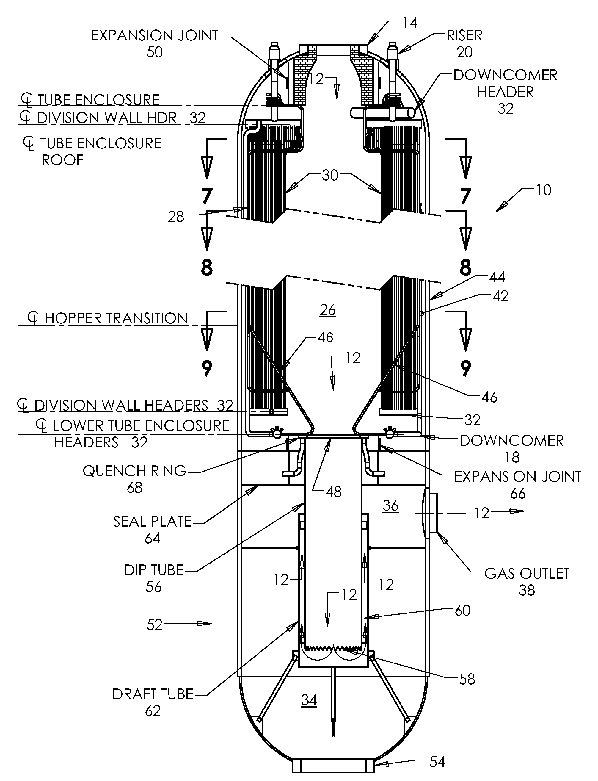
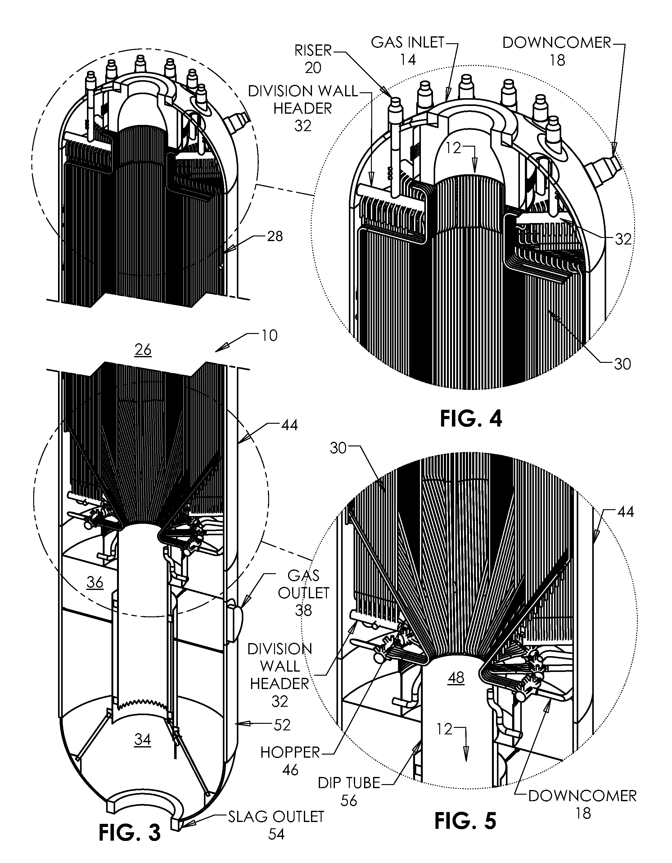
[0069]Referring now to FIGS. 6, 7, 8 and 9 there is shown the RSC 10 according to the present invention. As shown, the hot synthesis gas 12 enters through synthesis gas inlet 14 located at a top of the RSC 10. The hot synthesis gas 12 is conveyed downwardly through the flue 26 where the flue enclosure walls 28 and radiant heat transfer surface (division) walls 30 extract heat from the gas 12, reducing the latter's temperature. The bottom portion of the flue 26 is provided with hopper means 46, preferably frustoconical in cross section and having a throat 48. The hopper means 46 collects slag particles and directs the hot synthesis gas 12 downwardly towards the water bath region 34 at the lower portion 52 of the RSC 10. The water bath region 34 is typically filled with water during operation, and serves to quench and humidify the hot synthesis gas 12 before it exits from the RSC 10 via synthesis gas outlet 38. The water bath region 34 is also for receiving and cooling solids entraine...

second embodiment

[0074]As shown in FIG. 10, the RSC 10 according to the present invention is disclosed, and which involves the placement of convection heat transfer surface 70 adjacent the dip tube means 56 in order to extract additional heat from the synthesis gas 12 prior to conveying the synthesis gas 12 through the synthesis gas outlet 38. Advantageously, the convection heat transfer surface 70 comprises one or more banks of tubes arranged so that the synthesis gas 12 flows over the outside of the tubes. This convection heating surface 70 can be water or steam cooled. The banks of convection heating surface 70 may be provided anywhere around the perimeter of the dip tube means 56 and the tubes may be in any orientation. The convection heating surface 70 may employ the same fluidic circuitry (an integrated cooling approach) as is employed in the steam generating surface comprising the flue walls 28 and radiant heat transfer surfaces 30, thus eliminating the need for a separate cooling system. Alt...


PUM


Abstract

A radiant synthesis gas (syngas) cooler used to contain and cool the synthesis gas produced by a coal gasification process used in an IGCC power plant employs a compact radial platen arrangement which is less prone to fouling and/or plugging issues.

Description

[0001]This application claims priority to previously filed U.S. Provisional Patent Application No. 60 / 837,773, filed Aug. 15, 2006, titled “Compact Radial Platen Arrangement for Radiant Syngas Cooler,” which is hereby incorporated by reference as though fully set forth herein.FIELD AND BACKGROUND OF INVENTION[0002]The present invention relates generally to the field of coal gasification and, in particular, to a radiant synthesis gas (syngas) cooler for use in a coal gasification process. In one instance, the present invention relates to a radiant synthesis gas (syngas) cooler for an Integrated Gasification Combined Cycle (IGCC) power plant. In this embodiment, the radiant syngas cooler is used to contain and cool the synthesis gas produced by a coal gasification process used in the IGCC power plant.[0003]IGCC power plants firing solid fuels have traditionally been higher capital cost and have had lower operating availability and reliability than competing solid fuel technologies suc...

Claims


Application Information

Patent Timeline
IPC IPC(8): F28D7/00
CPCC10J3/485Y02E20/16C10J3/86C10J2300/093C10J2300/1687C10J2300/1884C10J2300/1892C10K1/101F28D7/00F28D7/0041F28D2021/0075F28F13/06Y02E20/18F28F2009/224C10J3/845
Inventor WESSEL, RICHARD A.KRAFT, DAVID L.FRY, STEVEN R.
Owner THE BABCOCK & WILCOX CO
Why Eureka
Try Eureka