Comparator Circuit and Method for Operating a Comparator Circuit

a comparator circuit and comparator technology, applied in the direction of pulse manipulation, multi-input and output pulse circuits, instruments, etc., can solve the problems of limiting the useable input voltage, offset errors and gain errors affecting the comparator accuracy, and low overall power consumption, and achieve high accuracy

Inactive Publication Date: 2008-02-28
GLOBALFOUNDRIES INC
View PDF5 Cites 21 Cited by
  • Summary
  • Abstract
  • Description
  • Claims
  • Application Information

AI Technical Summary

Benefits of technology

[0013] It is therefore an object of the invention to provide a comparator circuit which provides a rail-to-rail operation with high accuracy. Another object is to provide a method for operating the comparator circuit.
[0016] A comparator circuit is proposed for comparing a first voltage signal with a second voltage signal, the circuit comprising a first comparator and a second comparator and a selection unit for selecting one of the comparators depending on a selection condition. Advantageously, the gain of each comparator can be chosen independently from each other. Each comparator can be optimized for a different voltage regime, for example for high input voltages or low input voltages. Therefore, each comparator can work at its optimum. With an actual input signal present, the selecting unit advantageously selects one of the comparators according to its optimum voltage regime. Due to this digital selection of that one comparator working in its optimum range, the useable input voltage can be extended from single rail to a rail-to-rail, although each individual comparator can be a single-rail comparator. Due to the digital selection of the proper comparator, introduction of additional offsets and errors can be avoided, and mismatch compared to analog arrangements is avoided, where distortions / mismatch can occur. A degradation of operation speed can be prevented when using the inventive comparator circuit.
[0017] High accuracy with low process dependency, low voltage dependency as well as low temperature dependency can be achieved. By expanding the operating voltage range of the comparator circuit according to the invention, a higher resolution for measurements of on-chip data is available, such as thermal sensors, supply voltage sensors, noise sensors. A rail-to rail comparator circuit is provided, although single-rail comparators, preferably performance-optimized single-rail comparators, can be used. A self-calibration comparator mode of operation is possible, providing a still more exact calibration.
[0026] According to another preferred embodiment, the means comprises a voltage divider and a third comparator with an input port for a threshold voltage and an output port for a digital decision signal. This can be favorably used in a general comparator circuit. Preferably in this embodiment, the third comparator comprises an input port for a voltage signal which is also applied to one of the comparators. In this configuration the third comparator is working as a voltage plane detector. The third comparator can be a single-rail comparator of simple design.
[0031] At least one of the first and second comparators can be a single-rail-type unit. A mismatch as known from analog rail-to-rail solutions as well as a speed degradation can be avoided.
[0034] Preferably, the selection condition is the voltage signal being above or below a threshold voltage. The most accurate one of the two comparators can be selected depending on the threshold voltage. Being a digital selection, distortions, inaccuracies as well as speed degradation can be avoided. Further, one of the two comparators is preferably adapted for a first input voltage range and the other is adapted for a second input voltage range essentially different from the first input voltage range.

Problems solved by technology

Additionally, the overall power consumption is low, especially compared to so called flash analog-to-digital converters.
It is known that offset-errors and gain-errors affect the comparator accuracy.
Additionally, the comparator gain is a function of the common mode input voltage which results in limiting the useable input voltage and, further, an available input voltage swing is limited by the input buffer / sample-and-hold circuit, which is usually used at the comparator input.
But as already mentioned above, the comparator is one of the main sources of inaccuracy in such a circuitry.
Very low or very high input voltages close to the power supply rail voltages show a very low gain and yield high inaccuracy.
However, a rail-to-rail comparator or operational amplifier design introduces additional offset and error sources.
Full rail-to-rail operation can still not be achieved.

Method used


Image

  • Comparator Circuit and Method for Operating a Comparator Circuit
  • Comparator Circuit and Method for Operating a Comparator Circuit
  • Comparator Circuit and Method for Operating a Comparator Circuit

Examples


Embodiment Construction

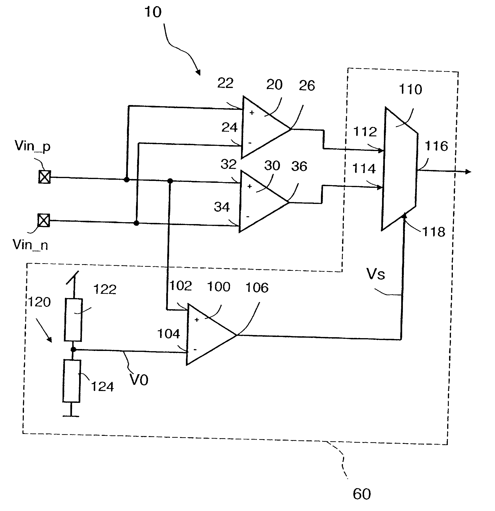
[0045] A preferred embodiment of the invention is depicted in FIG. 1. A comparator circuit comprises a first comparator 20 and a second comparator 30 and a selection unit 60. The selection unit 60 is indicated with a dotted line. In this embodiment, the comparator circuit represents a high accuracy rail-to-rail comparator building block.

[0046] An input voltage signal Vin_p is fed into an input port 22 and an input voltage signal Vin_n is fed into an input port 24 of the first comparator 20. An output port 26 of the first comparator 20 feeds an output signal to the selection device 60.

[0047] An input voltage signal Vin_p is fed into an input port 32 and an input voltage signal Vin_n is fed into an input port 34 of the second comparator 30. An output port 36 of the second comparator 30 feeds an output signal to the selection unit 60.

[0048] Most preferably, the first comparator 20 is equipped with pMOS transistors and therefore adapted for low input voltage levels and the second com...


PUM


Abstract

A comparator circuit for comparing a first voltage signal to a second voltage signal is described. The comparator circuit includes a first comparator and a second comparator and a selection unit for selecting one of the comparators depending on a selection condition. The invention also provides a method for operating a comparator circuit.

Description

CLAIM OF PRIORITY [0001] This application claims priority to Application No. 06117795.2 filed Jul. 25, 2006, the entire content of which is incorporated by reference herein. BACKGROUND OF THE INVENTION [0002] The invention relates to a comparator circuit and a method for operating a comparator circuit according to the preambles of the independent claims. [0003] Successive approximation analog-to-digital converters (ADC) are well known in the art. Such ADCs use a comparator to reject ranges of voltages, eventually settling on a final voltage range, and convert one bit per cycle. A typical successive approximation ADC comprises a reference voltage generator, a comparator and a successive approximation register. A general description of this kind of ADCs can be found for example in Allen / Holberg: “CMOS Analog Circuit Design”, Oxford University Press 2002, 668-672. [0004] A single-rail comparator supports a limited input voltage range only. Normally asymmetric input range, starting at s...

Claims


Application Information

Patent Timeline
Patent Type & Authority Applications(United States)
IPC IPC(8): H03K5/22
CPCG03F7/70516
Inventor EHRENREICH, SEBASTIAN
Owner GLOBALFOUNDRIES INC
Why Eureka
Try Eureka