

Prevention of quantum dot quenching on metal surfaces
a technology of metal surfaces and quantum dots, applied in the direction of non-metal conductors, instruments, conductors, etc., can solve the problems of limiting the current use of quantum dots on such metallic surfaces, and the possibility of quantum dots easily rubbing off of substrate materials
- Summary
- Abstract
- Description
- Claims
- Application Information
AI Technical Summary
Benefits of technology
Problems solved by technology
Method used
Image

Examples
example 1
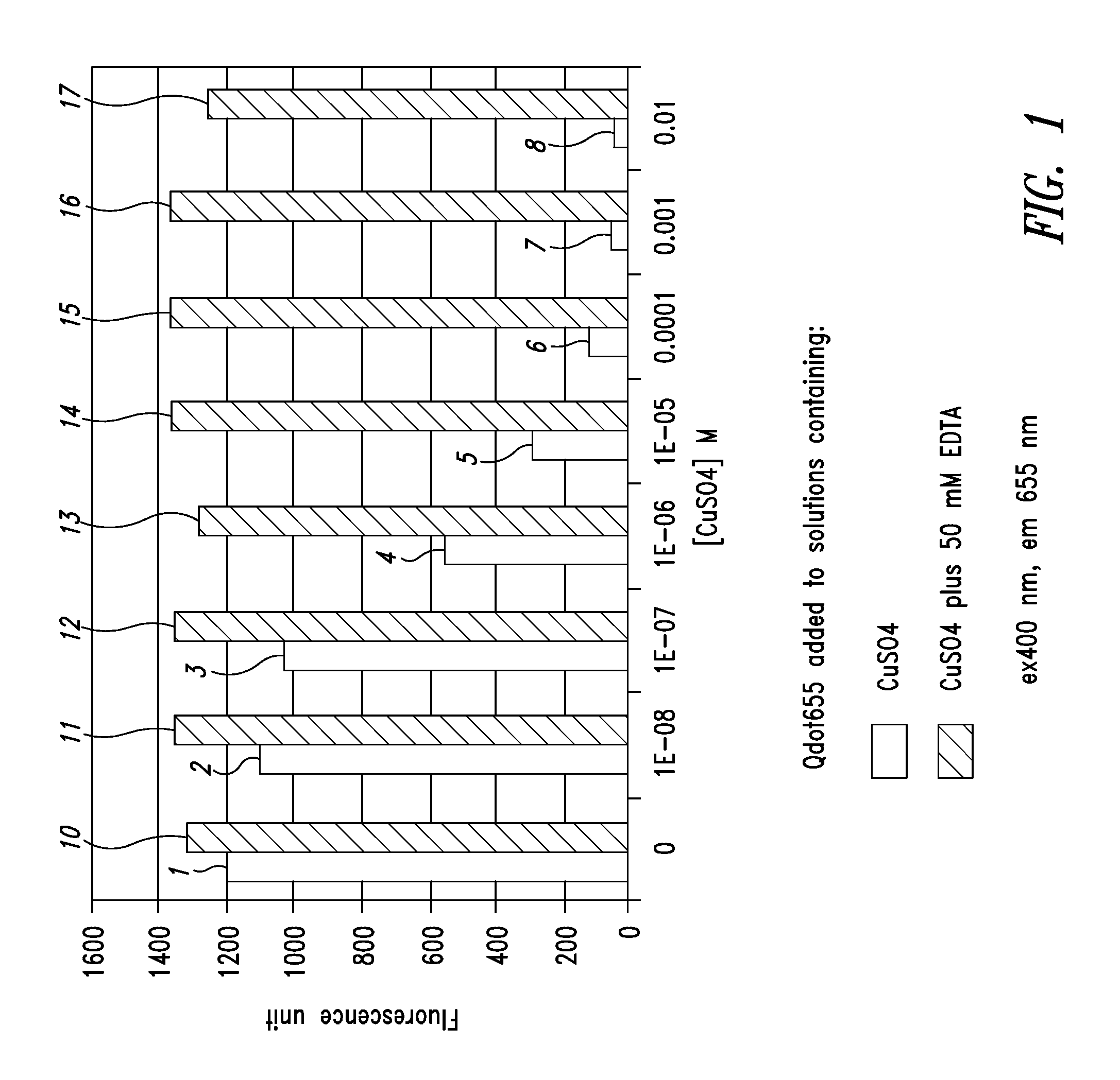
[0107]FIG. 1 is a graph illustrating the difference between the fluorescence of quantum dots in a standard formulation and a formulation with chelating agents added. In the graph, the amount of fluorescence for the different formulations is shown for various concentrations of CuSO4 using quantum dots, which fluoresce at 655 nanometers wavelength. The left-hand bar of each pair of bars shows the amount of fluorescence in the formulation for different concentrations of CuSO4 without a chelating agent and on the right-hand side of each pair of bars, the amount of fluorescence of the quantum dots with a chelating agent present.
[0108] In the first bar of the graph, the fluorescence level 1 is approximately 1,200 for a suspension composed of water and quantum dots emitting at 655 nanometers. On the right-hand side 10 of the first bar, a chelating agent has been added, increasing the fluorescence to approximately 1,300. In this first example, no CuSO4 has been added to the formulation. Th...
example 2
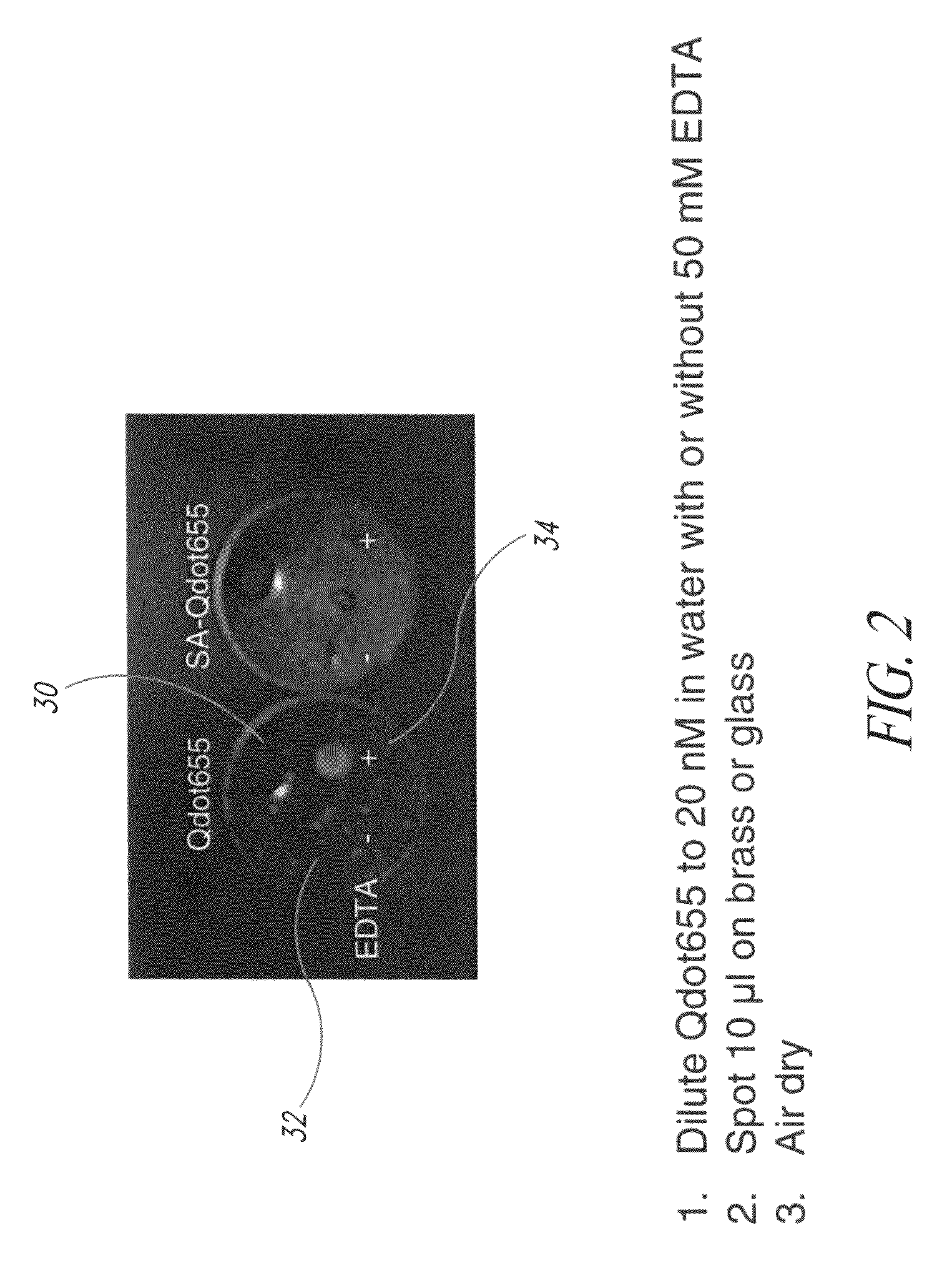
[0110]FIG. 2 illustrates two droplets of quantum dot formulations applied to a brass marker, one droplet having a chelating agent and the other does not have a chelating agent present. In the specific example of FIG. 2, quantum dots exhibiting fluorescence at 655 nanometers were suspended in water at a strength of 20 nM. In the first example shown on the left, no chelating agent was added and in the example shown on the right, a chelating agent was added to the formulation. In the embodiment of FIG. 2, the chelating agent added was 50 mM of EDTA. Each of the two formulations was then applied to a brass marker 30 as illustrated in FIG. 2. The application to the brass tag 30 was made by a droplet of 10 μl of the respective quantum dot formulations on the brass marker, after which it was allowed to air dry. The formulation without the chelating agent is in region 32 on the left-hand side of the tag 30, and the formulation with the chelating agent is in region 34. The marker was then ex...
example 3
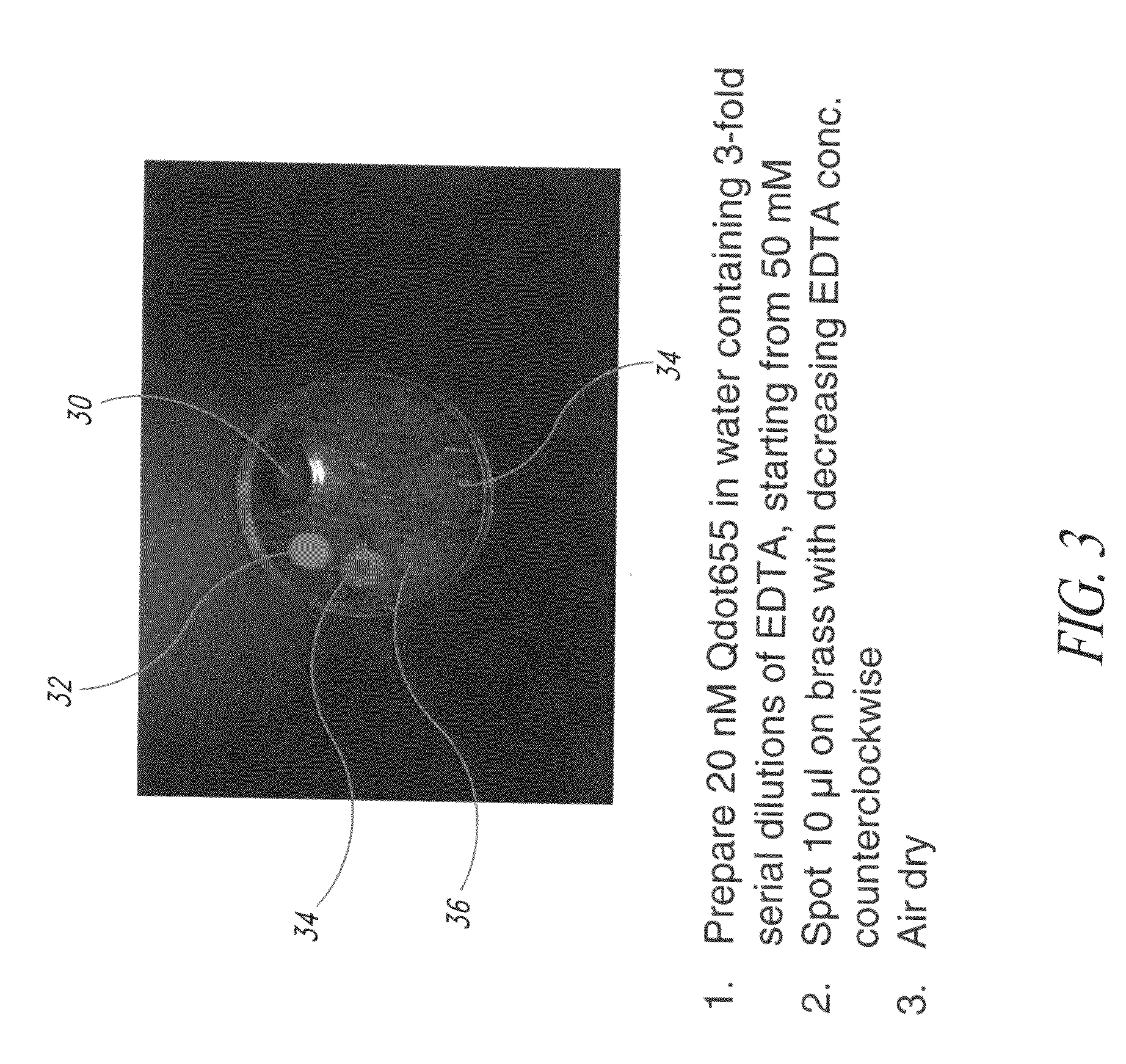
[0112]FIG. 3 illustrates examples of different quantities of the chelating agent being added to the formulations in order to test a preferred level of chelating agent to be added to a formulation. According to the example as shown in FIG. 3, 20 nM of quantum dots that fluoresced at 655 nanometers were suspended in a carrier material (e.g., water). Various concentrations of the chelating agent were added to the fluid. Each of the formulations was applied to the brass tag 30 in order to test the efficacy of different levels of the chelating agent present in the formulation. The brass tag 30 was thereafter exposed to ultraviolet light and the photograph taken as shown in FIG. 3. In the first formulation as shown in region 32, chelating agent to a strength of 50 mM of EDTA was present. In the formulation in the second region 34, a strength of approximately 17 mM of EDTA was present. In the formulation which was deposited at the third location 36, approximately 6 mM of EDTA were present,...
PUM
 Abstract
Description
Claims
Application Information