Technique for electrically bonding solar modules and mounting assemblies

a solar module and mounting system technology, applied in the direction of heat collector mounting/support, connection contact member material, lighting and heating apparatus, etc., can solve the problems of difficult handling and assembly on the roof, and the current method of installing proper bonding devices for photovoltaic (pv) modules and other types of solar modules is both expensive and time-consuming

Active Publication Date: 2008-03-06
FTC SOLAR INC
View PDF64 Cites 186 Cited by
  • Summary
  • Abstract
  • Description
  • Claims
  • Application Information

AI Technical Summary

Problems solved by technology

Current methods of installing proper bonding devices for PhotoVoltaic (PV) modules and other types of solar modules is both expensive and time consuming.
Though a simple solution, it is time consuming to bond modules in this manner due to the need to wrap the grounding wire around each screw.
Also, since the parts involved with this method are small and discrete, they are hard to handle and assemble on a rooftop during typical installations.
Although use of a bonding lug does not necessitate wrapping the grounding wire, the installation is also labor intensive and awkward because of its two-step process: first the lug has to be fastened to the frame of the PV module and then the wire must be clamped into the lug using a second fastener such as a set screw.

Method used


Image

  • Technique for electrically bonding solar modules and mounting assemblies
  • Technique for electrically bonding solar modules and mounting assemblies
  • Technique for electrically bonding solar modules and mounting assemblies

Examples


Embodiment Construction

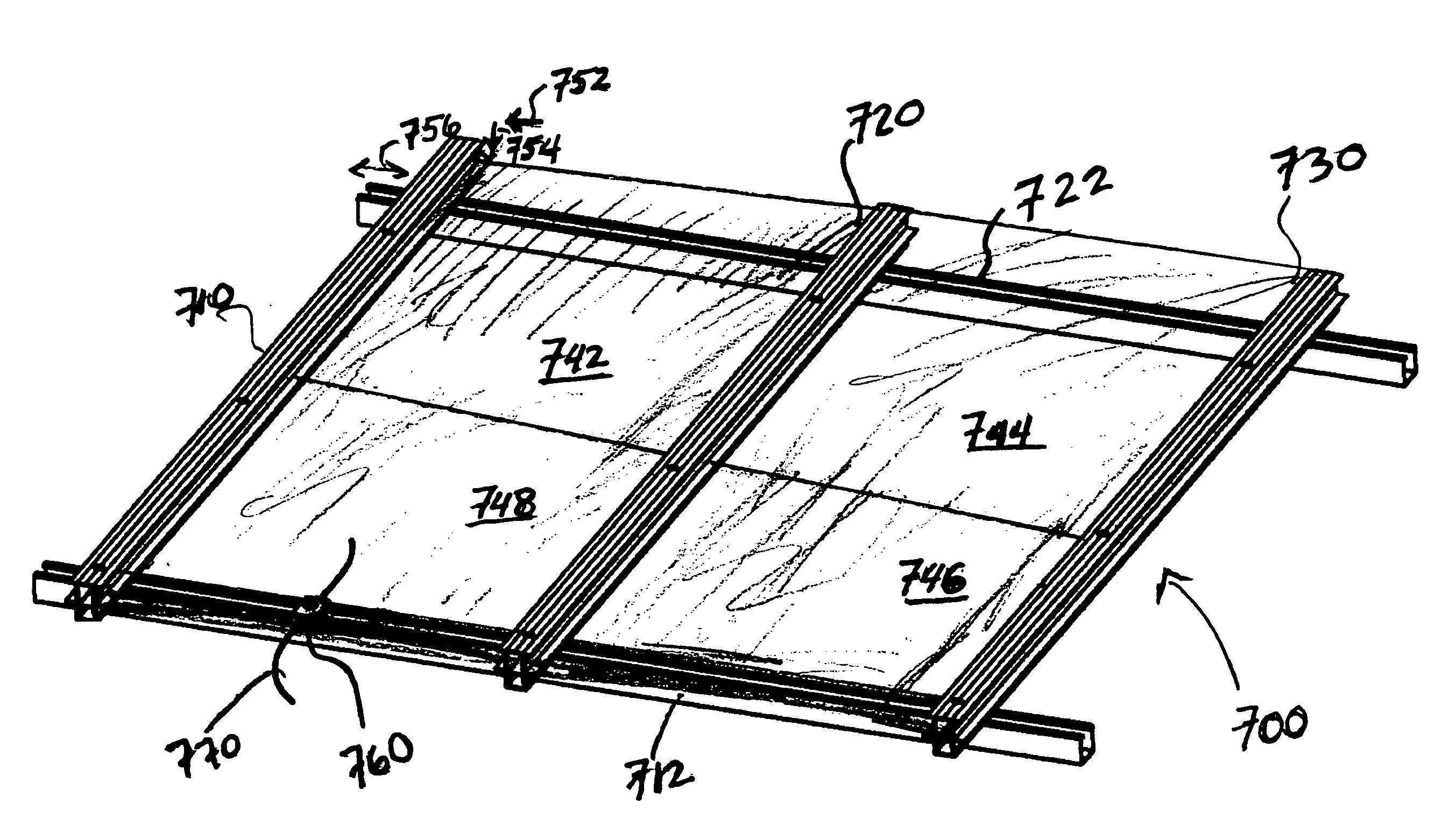
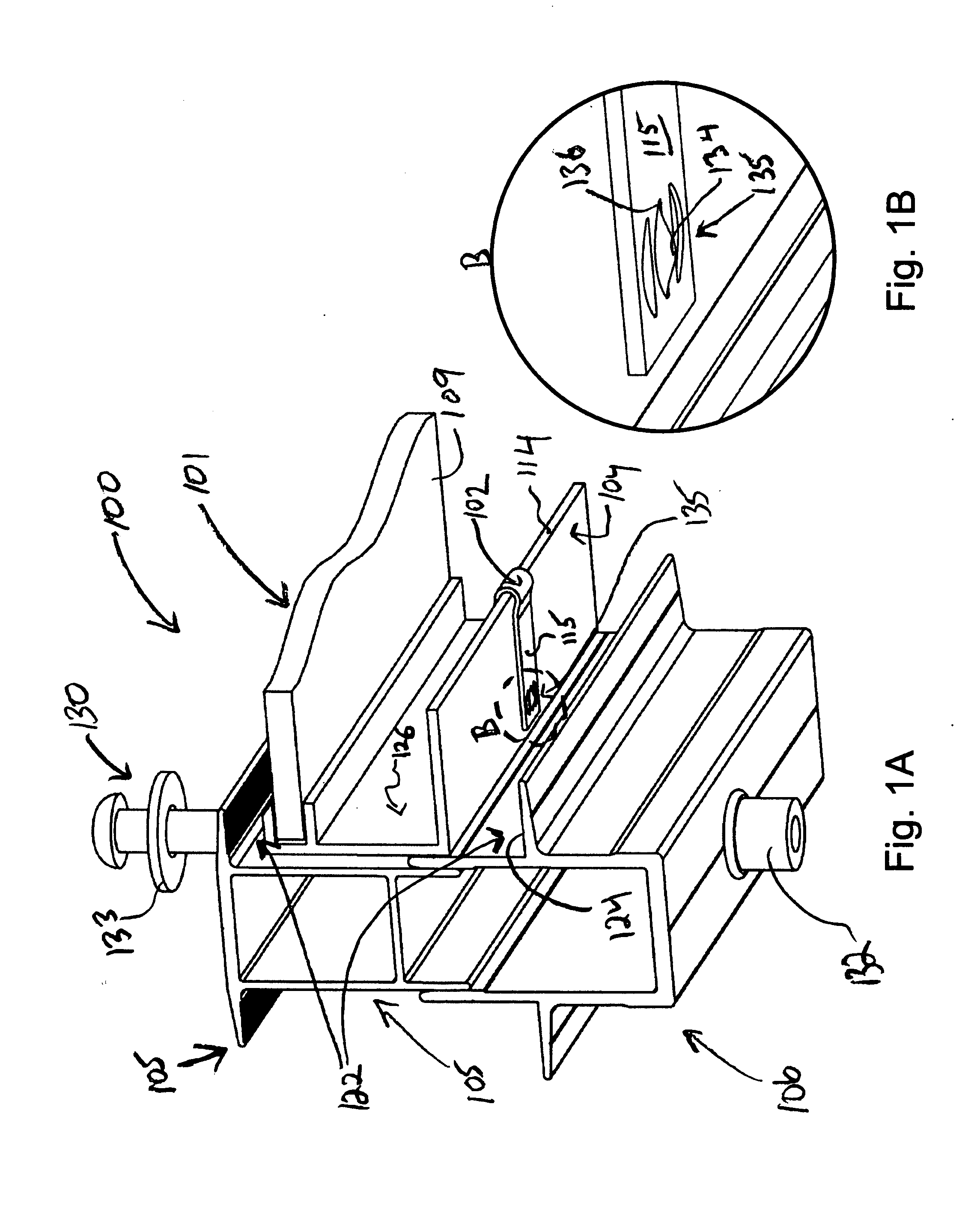
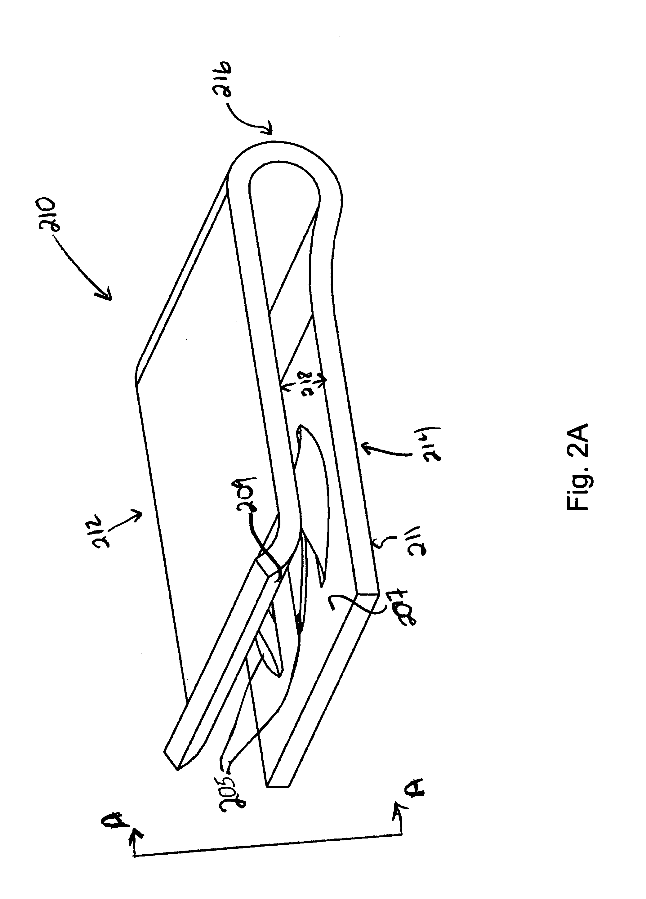
[0016]Embodiments described herein enable use of conductive elements on mounting assemblies for solar modules, for purpose of creating bonding or grounding points. As described, embodiments provide that such conductive elements are included between the engagement of the solar modules and the rail assemblies or support structures that hold the solar modules in place. Conductive paths for bonding or grounding purposes may then be formed that require minimal additional steps in assembling the mounting assembly as a whole. One or more embodiments enable such bonding or grounding features to be incorporated into the solar module array with assembly steps that eliminate the need for running grounding / bonding elements as separate assembly requirements.

[0017]According to an embodiment, a mounting system is provided for an array of solar modules. The mounting system includes one or more rail assemblies that extend lengthwise in a first direction to support a plurality of solar modules that c...


PUM


Abstract

A mounting system is provided for an array of solar modules. The mounting system includes one or more rail assemblies that extend lengthwise in a first direction to support a plurality of solar modules that comprise the array. Each of the one or more rail assemblies may be configured to compress in order to retain an edge section of one or more of the plurality of solar modules in an operable position. A conductive element may be positioned to bond the edge section of at least one of the plurality of solar modules with at least a section of the rail assembly that retains that edge section in the operable position, so as to form a conductive path for electrical current.

Description

RELATED APPLICATIONS[0001]This application claims benefit of priority to Provisional U.S. Patent Application No. 60 / 824,260, filed Aug. 31, 2006, and entitled METHODS FOR GROUNDING SOLAR MODULES AND MOUNTING SYSTEMS. The aforementioned priority application is hereby incorporated by reference.TECHNICAL FIELD[0002]The disclosed embodiments relate generally to the field of solar modules and mounting systems. In particular, the disclosed embodiments relate to mechanisms for electrically bonding or grounding solar modules and mounting systems for solar modules.BACKGROUND[0003]Current methods of installing proper bonding devices for PhotoVoltaic (PV) modules and other types of solar modules is both expensive and time consuming. Most electrical codes require a grounding wire to be mechanically bonded to each PV module frame within an array of PV modules as well as to the overall mounting system itself.[0004]There are two prevalent bonding methods that represent the state of the art. One us...

Claims


Application Information

Patent Timeline
Patent Type & Authority Applications(United States)
IPC IPC(8): H01L31/048
CPCF24J2/5207F24J2/5211F24J2/5258F24J2002/4665H01L31/0422H02S20/00H01R4/64H01R4/66Y02B10/12Y02E10/47Y02E10/50H01R4/26F24S25/20F24S25/35F24S25/636F24S2025/6004H02S20/23Y02B10/10
Inventor PLAISTED, JOSHUA REEDWEST, BRIAN
Owner FTC SOLAR INC
Why Eureka
Try Eureka