Electric potential difference detection method and scanning probe microscope
a scanning probe and detection method technology, applied in the direction of instruments, mechanical measuring arrangements, mechanical roughness/irregularity measurements, etc., can solve the problems of difficult to judge from the observation image obtained whether, measurement becomes impossible, and it is difficult to obtain accurate observation images, etc., to accurately perform the observation of the sample, and easily and accurately detect the existence/nonexistence
- Summary
- Abstract
- Description
- Claims
- Application Information
AI Technical Summary
Benefits of technology
Problems solved by technology
Method used
Image
Examples
first embodiment
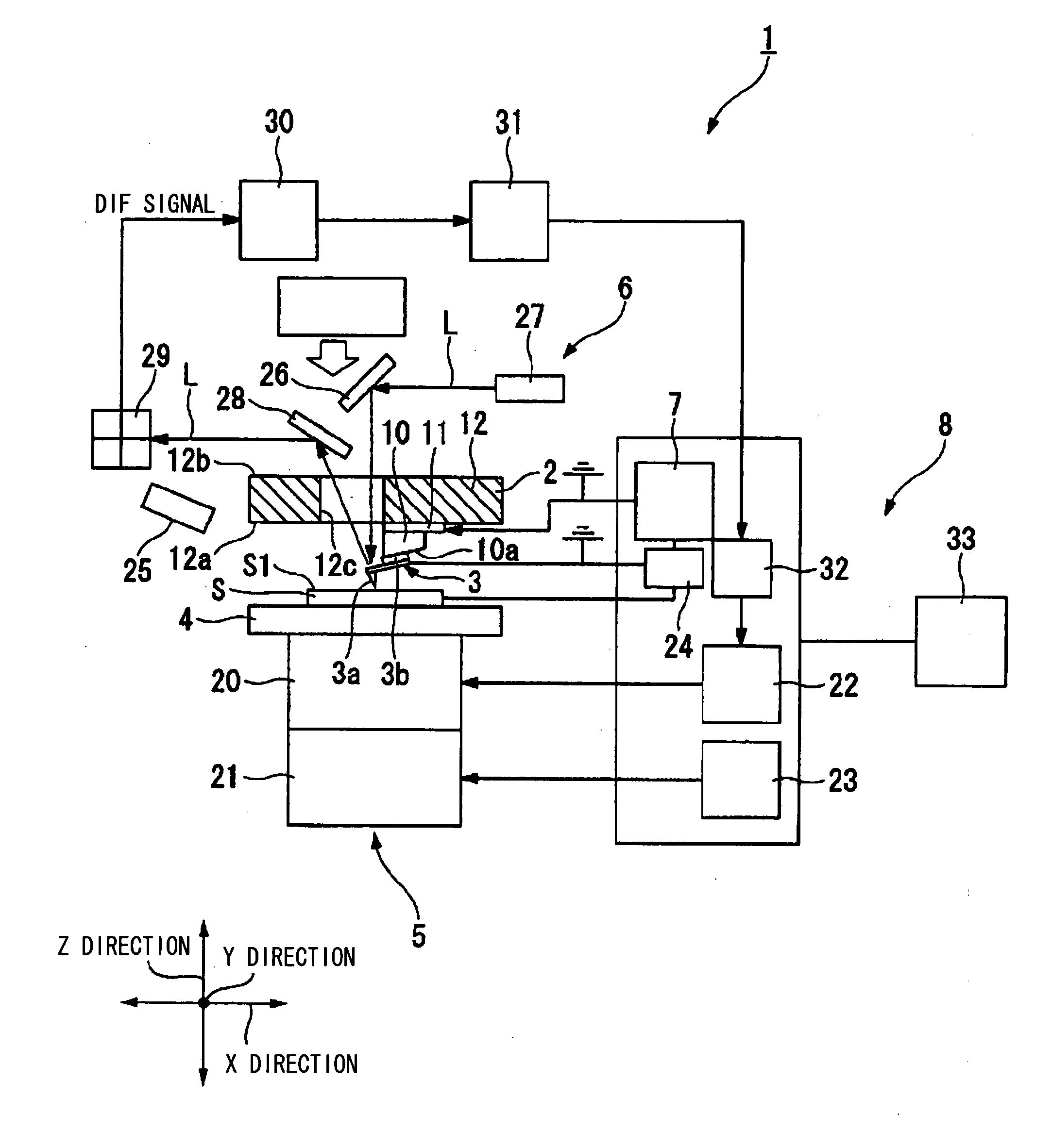
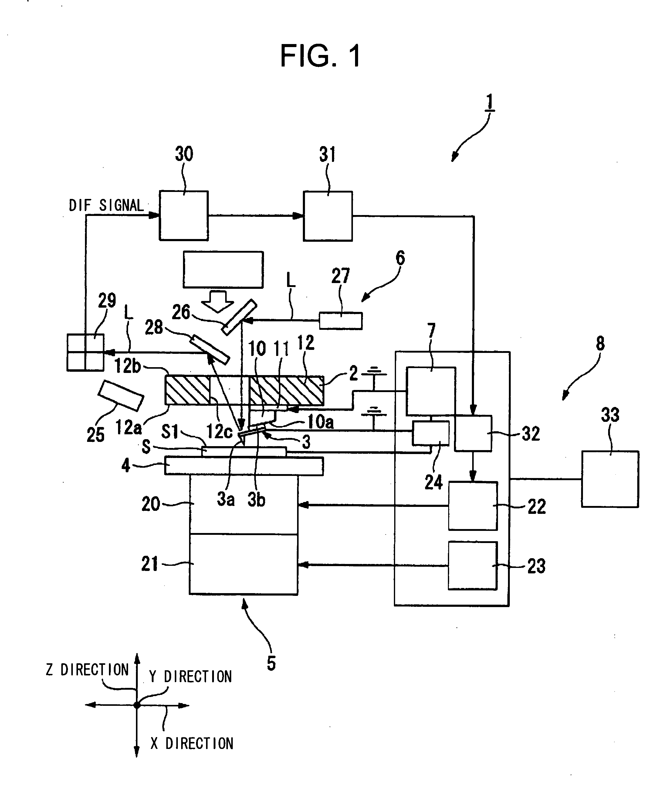
[0068]FIG. 1 and FIG. 5 show a first embodiment concerned with this invention. FIG. 1 shows a schema view of a scanning probe microscope of the present embodiment. Incidentally, in the present embodiment, there is explained with a sample scan system moving a sample side in a three-dimensional direction being made an example. As shown in FIG. 1, a scanning probe microscope 1 of the present embodiment comprises a cantilever holder 2, a cantilever 3 having in its tip a probe 3a, supported under an overhung state in a main body part 3b of its base end side and fixed to the cantilever holder 2, a sample base 4 mounting a sample S disposed while facing on the probe 3a, a movement member 5 relatively scanning the probe 3a and the sample S in an XY direction parallel to a sample surface S1 and relatively moving them in a Z direction perpendicular to the sample surface S1, a measurement member 6 measuring a displacement of a vibration state of the cantilever 3, and a controller 8 which, as t...
second embodiment
[0098]FIG. 16 to FIG. 19 show a second embodiment concerned with this invention. In this embodiment, the same reference numeral is applied to a member common to the member used in the above-mentioned embodiment, and its explanation is omitted.
[0099]As shown in FIG. 16, in a scanning probe microscope 50 of this embodiment, as a voltage application member 51, between the sample S and the cantilever 3, a DC electric source 52 is connected together with the AC signal generator 24. Therefor, in a voltage detection process, by the voltage application member 51, it is possible to apply a DC voltage together with the AC voltage while being superimposed. Next, there are explained about a detection method of the electric potential difference and an observation method of the sample on the basis of the detection result in the scanning probe microscope 50.
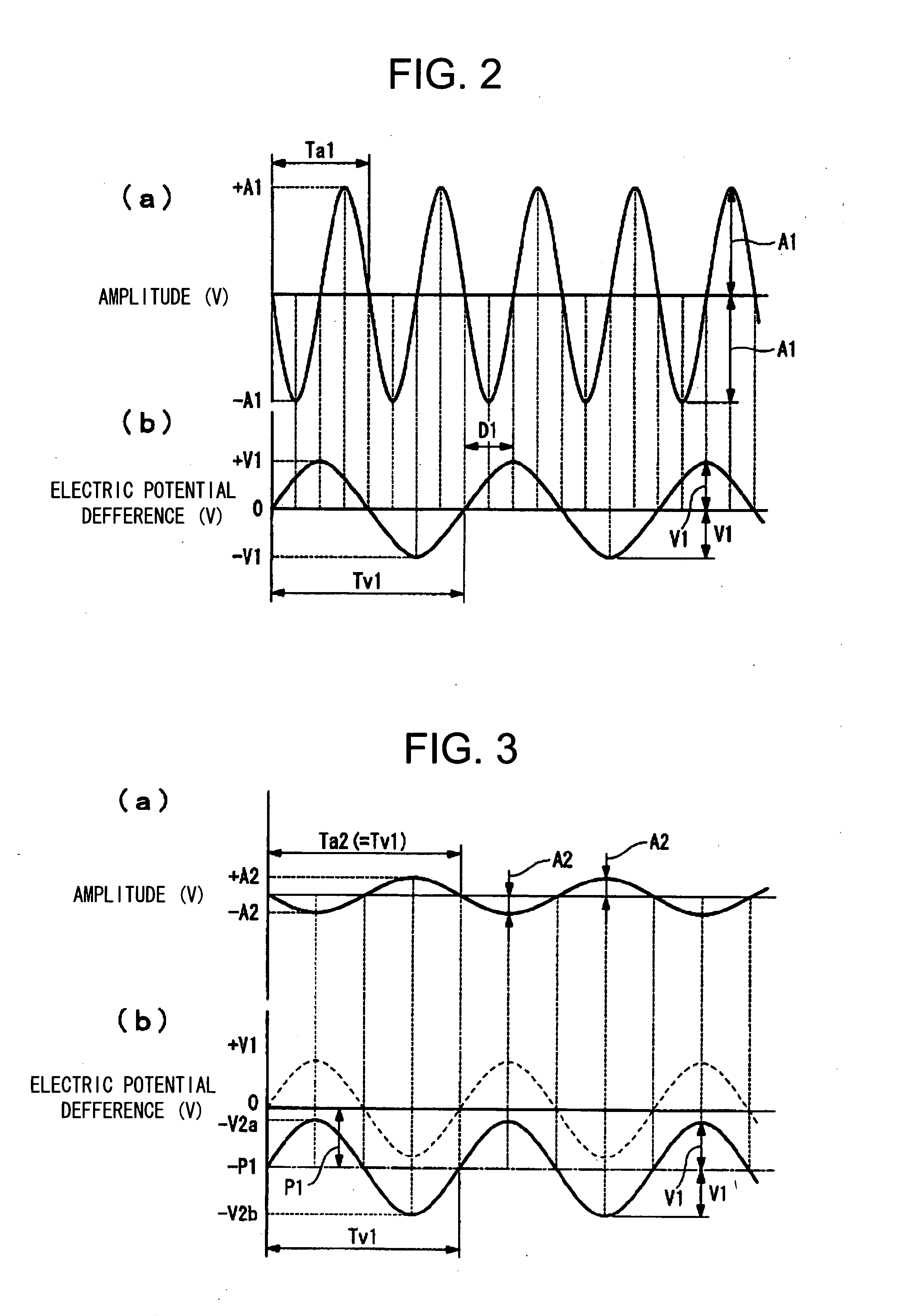
[0100]First, as shown in FIG. 17, only the AC voltage is applied without applying the DC voltage. It is supposed that an amplitude of the AC v...
PUM
 Abstract
Description
Claims
Application Information
 - R&D
- Intellectual Property
- Life Sciences
- Materials
- Tech Scout
- Unparalleled Data Quality
- Higher Quality Content
- 60% Fewer Hallucinations
Browse by: Latest US Patents, China's latest patents, Technical Efficacy Thesaurus, Application Domain, Technology Topic, Popular Technical Reports.
© 2025 PatSnap. All rights reserved.Legal|Privacy policy|Modern Slavery Act Transparency Statement|Sitemap|About US| Contact US: help@patsnap.com


