
Mold body and method of manufacturing the same

Inactive Publication Date: 2008-03-06
SONY CORP
View PDF0 Cites 14 Cited by
  • Summary
  • Abstract
  • Description
  • Claims
  • Application Information

AI Technical Summary

Benefits of technology

[0008] The present application addresses the above-identified issues associated with the developing technologies. One effect of the present embodiments is to provide a mold body having, incorporated therein, an IC tag obtainable at low cost, less causative of quality degradation induced by impact and changes in temperature and humidity, less susceptible to illegal actions, and capable of preventing the reliability -from degrading over a long period, and a method of manufacturing the same.
[0014] The mold body of the illustrative embodiment shows an excellent long-term reliability, because a semiconductor device of the IC tag is exposed to only a small damage in the process of molding, and doubly sealed. In addition, restriction on the module is moderated, because soldering failure due to re-melting of solder inside the IC tag module is avoidable, and thereby electronic circuits to be sealed can be bonded by soldering at low costs.
[0015] According to another illustrative embodiment, a product-specific ID, applicable to copyright protection and charging, can be attached by integrated molding and sealing, at low costs.

Problems solved by technology

However, the bar code label, less durable against scratching and fouling, and often placed on packaging materials, rather than on products to be packaged therein was not practical when considered on the basis of life cycle spanning from manufacture to disposal of the products.
Even protection of the label with a resin film or the like does not give a fundamental solution against scratching and fouling, whereas the need of adhesion of the label onto products raises another problem of adhesion failure or separation, or need of space for adhesion.
However, the main stream of way of mounting the IC tag onto commodities at present is generally such as bonding and placing it after being processed in a form of an IC tag sheet (a sheet referred to as “inlet”, processed in a form of a film), needing a considerable number of process steps and costs.
It has also many issues in durability and security, with fear of raising failures ascribable to breakage and deterioration so that it is considered as inappropriate as a means for mounting onto electronic device as durable consumer goods.
Another issue of the IC tag, resides in its high cost for mounting through adhesion or bonding, and poor durability.

Method used


Image

  • Mold body and method of manufacturing the same
  • Mold body and method of manufacturing the same
  • Mold body and method of manufacturing the same

Examples


example 1

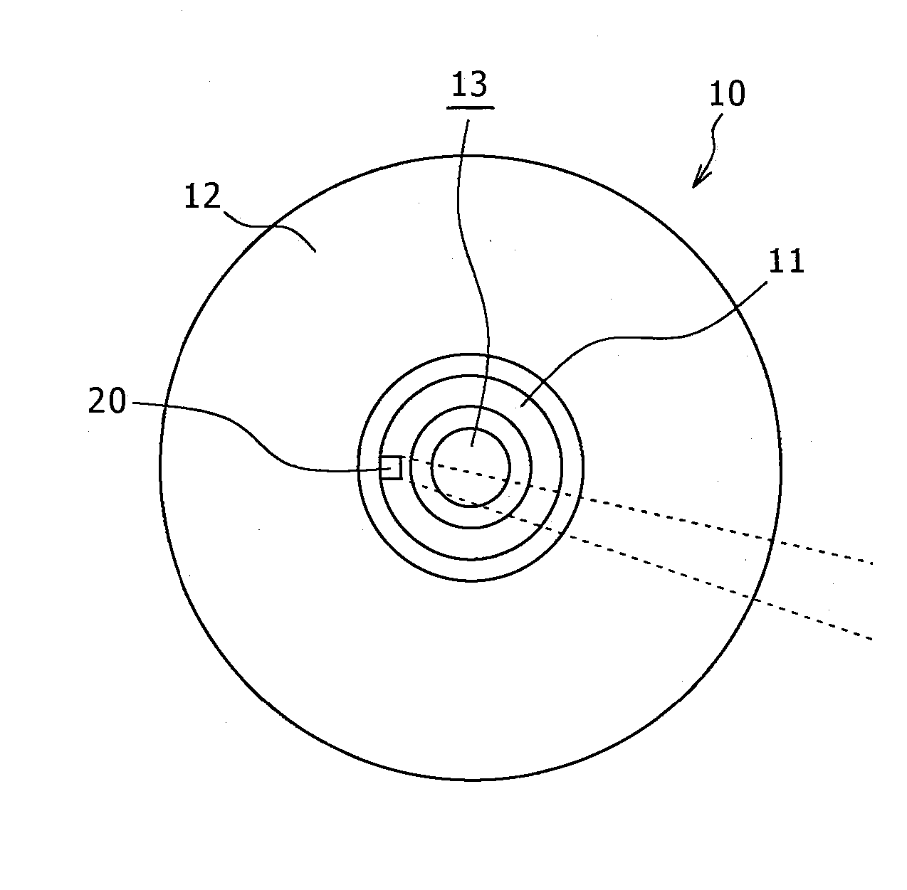
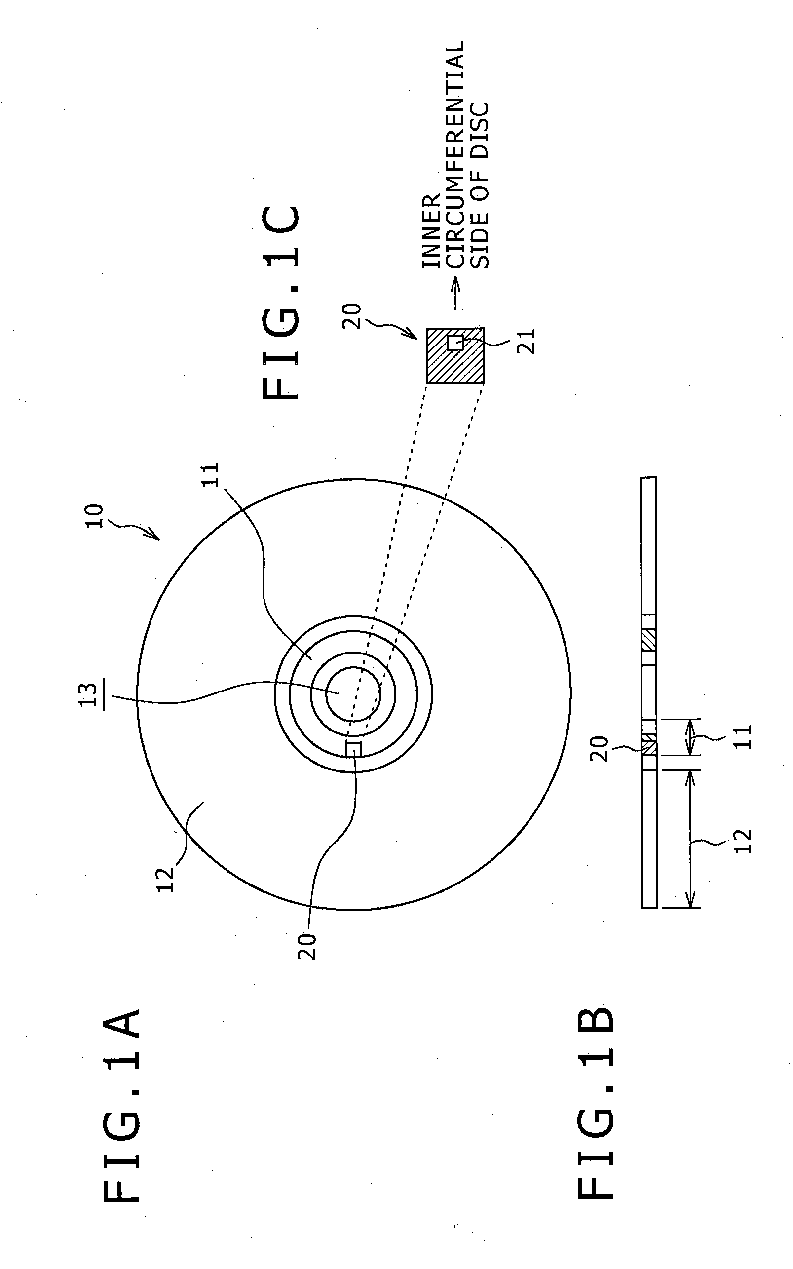
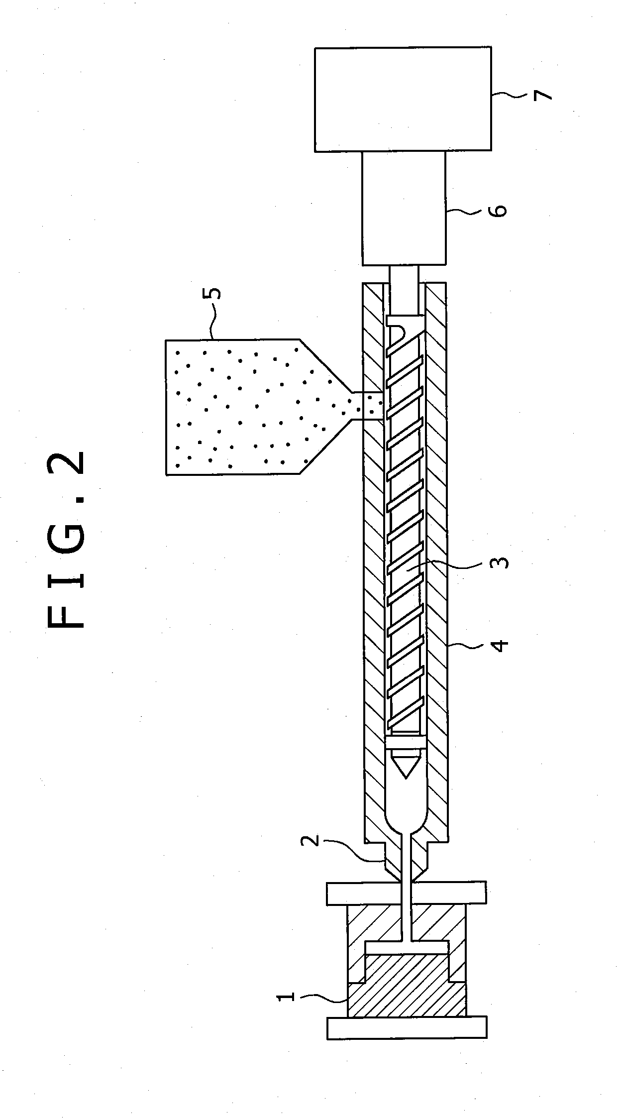
[0094] Injection molding was carried out using three types of molding materials, involving a low-melting-point plastic mainly composed of polylactic acid, polystyrene and polycarbonate, while varying the molding temperature. The IC tag module and the molding materials are shown below: [0095] (1) IC tag module: “M-Tag (ACCUWAVE-IM0505-SLI)” from Dai Nippon Printing Co., Ltd. (5.45-mm square, 0.76 mm thick, with an integrated antenna having a communication frequency in 13.56-MHz band); [0096] (2) molding material: selected from three following materials: [0097] thermoplastic resin mainly composed of polylactic acid (H100J, from Mitsui Chemicals, Inc.); [0098] thermoplastic resin mainly composed of polystyrene (GPPS HF77, from PS Japan); and [0099] thermoplastic resin mainly composed of polycarbonate (Panlite L-1225L, from Teijin chemicals, Ltd.).

[0100] At the start of the injection molding, the IC tag module was preliminarily placed on the horizontal portion of the die on the movable...


PUM

PropertyMeasurementUnit
Temperatureaaaaaaaaaa
Shapeaaaaaaaaaa
Areaaaaaaaaaaa

Abstract

A mold body and method of manufacturing the mold body is provided. The mold body includes a resin-molded IC tag module with an integrated antenna and a molding material sealing the IC tag module. The molding material is any one simple thermoplastic resin selected from the consisting of aliphatic polyester, polystyrene, methyl polymethacrylate, polyacetal, polyethylene, polypropylene, polyamide 11 and polyamide 12, or a material containing any one or more of the thermoplastic resins. The method of manufacturing a mold body includes providing a resin-molded IC tag module with an integrated antenna; and sealing at the same time with injection molding the resin-molded IC tag module by using the thermoplastic resin or the thermoplastic material.

Description

CROSS REFERENCES TO RELATED APPLICATIONS [0001] The present application claims priority to Japanese Patent Application No. 2006-212976 filed on Aug. 4, 2006, the entire content of which being incorporated herein by reference.BACKGROUND [0002] The present disclosure relates to a mold body configured as sealing a resin-molded IC tag module with an integrated antenna, and in particular to an enclosure of an electronic device or optical disc mold body having an IC tag module incorporated therein. [0003] There has been known an inexpensive bar code label, as a power-source-less, non-contact ID, for more efficient distribution and management, and traceability of products. However, the bar code label, less durable against scratching and fouling, and often placed on packaging materials, rather than on products to be packaged therein was not practical when considered on the basis of life cycle spanning from manufacture to disposal of the products. Even protection of the label with a resin fi...

Claims


Application Information

Patent Timeline
IPC IPC(8): B32B3/02B29C45/00G11B7/2535
CPCB29C45/14639B29C45/14836G11B23/0042B29L2017/003B29L2017/005B29C2045/14852
Inventor KANNO, MASAYOSHIAOKI, YUYA
Owner SONY CORP
Learn More