Eureka AIR delivers breakthrough ideas for toughest innovation challenges, trusted by R&D personnel around the world.

Method and apparatus for manufacturing band stop filter

Inactive Publication Date: 2008-03-06
DONGBU HITEK CO LTD
View PDF4 Cites 0 Cited by
  • Summary
  • Abstract
  • Description
  • Claims
  • Application Information

AI Technical Summary

Benefits of technology

[0011]The present invention provides a BSF fabrication method that produces a pattern using a hologram lithography and a photolithography, thereby reducing the chip size.
[0013]In one embodiment, the hologram lithography is able to change a period of a desired pattern, a period interval, a pattern radius, and a pattern shape using constructive and destructive interference of light.

Problems solved by technology

When the passive components are used, individual components may occupy a very large area on a chip.
Accordingly, it may be difficult to reduce the chip size when implementing a System-On-Chip (SOC) architecture.

Method used


Image

  • Method and apparatus for manufacturing band stop filter
  • Method and apparatus for manufacturing band stop filter
  • Method and apparatus for manufacturing band stop filter

Examples


Embodiment Construction

[0023]Reference will now be made in detail to embodiments consistent with the present invention, examples of which are illustrated in the accompanying drawings. Wherever possible, the same reference numerals will be used to refer to the same or like parts.

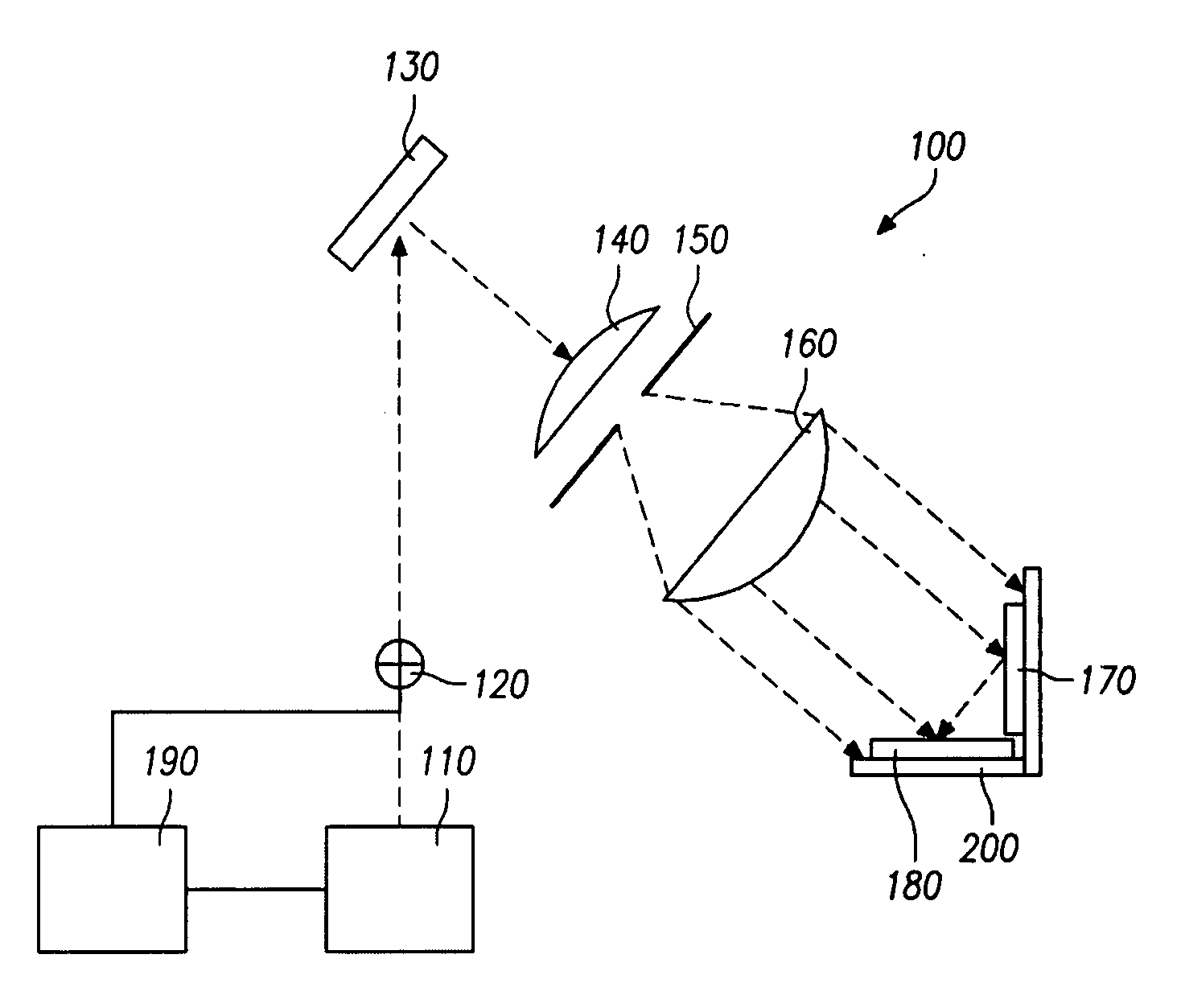
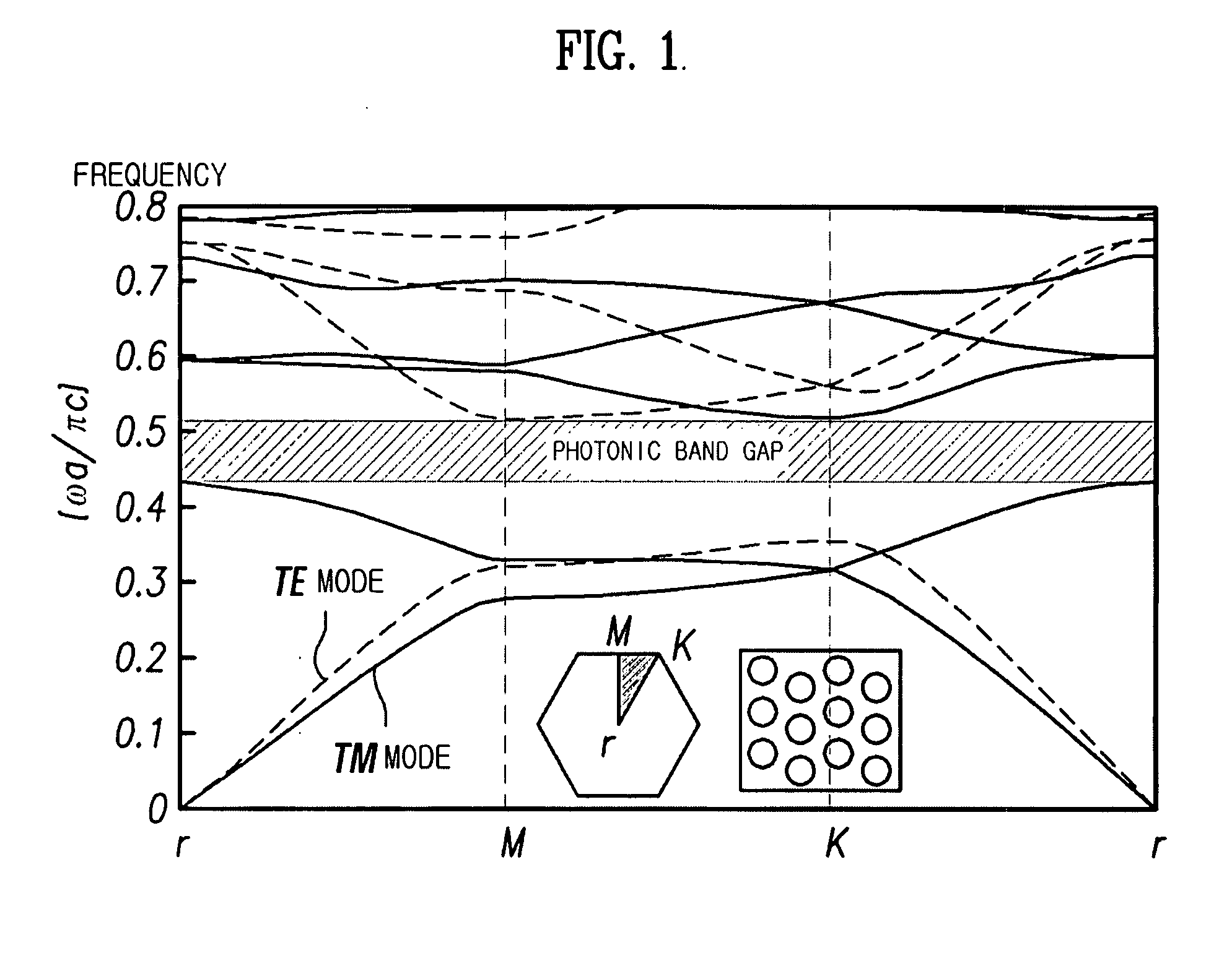
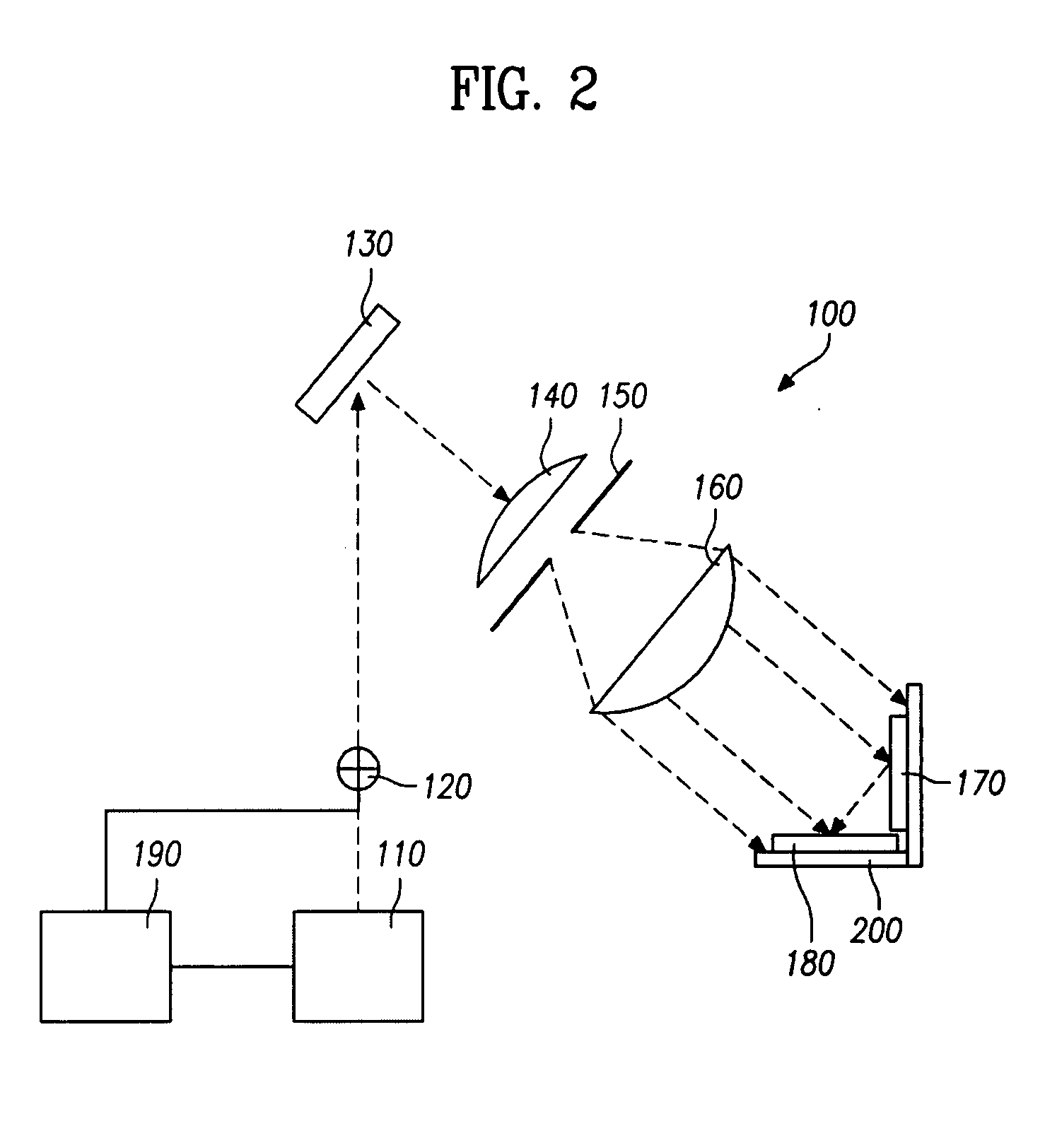
[0024]FIG. 1 illustrates a forbidden band of a photonic crystal of a two-dimensional (2D) triangular lattice according to an embodiment consistent with the present invention. FIG. 2 illustrates an apparatus for manufacturing a band stop filter according to an embodiment consistent with the present invention. FIG. 3 illustrates a band stop filter fabricated according to an embodiment consistent with the present invention. FIG. 4 illustrates the operations of the band stop filter according to an embodiment consistent with the present invention.

[0025]An apparatus 100 (i.e., a hologram lithography) for manufacturing a band stop filter consistent with the present invention will be described with reference to FIG. 2.

[0026]Referring to FI...


PUM


Abstract

A method and an apparatus for manufacturing a band stop filter are disclosed. In one aspect, the method uses hologram lithography to produce the band stop filter of a smaller size without the need of a mask.

Description

[0001]This application claims the benefit of priority from Korean Patent Application No. 10-2006-0085487, filed on Sep. 6, 2006, the entire contents of which are incorporated herein by reference.BACKGROUND[0002]1. Technical Field[0003]The present invention relates generally to a method and an apparatus for manufacturing a band stop filter, and more particularly, to a method and an apparatus for manufacturing a band stop filter capable of fabricating a pattern using a hologram lithography and a photolithography.[0004]2. Related Art[0005]Generally, a lithography process in the semiconductor industry refers to a process for transcribing patterns. The lithography process is important in the fabrication of integrated circuits (IC). The lithography process may be classified into an optical lithography based on light, an electron-beam lithography based on electron beams, and an X-ray lithography based on X-rays.[0006]Optical lithography technology may employ ultraviolet (UV) rays as the li...

Claims


Application Information

Patent Timeline
IPC IPC(8): G03F7/20H01S3/08
CPCB82Y20/00G02B6/1225H01P1/2005G03F7/70408G03F7/7045G03F7/0005
Inventor KIM, SANG JUNE
Owner DONGBU HITEK CO LTD
Why Eureka
Eureka Blog
Learn More